
A flashing beacon has many uses. It can be employed as a distress signal on highways or as a direction pointer for parking lots, hospitals, hotels, etc. Here we present a flashing beacon that uses well-known regulator IC LM317T. As LM317T regulator can deliver more than 1 amp. A small 12V, 10W bulb with a high-quality reflector can serve as a good visible blinker.
Flashing beacon circuit
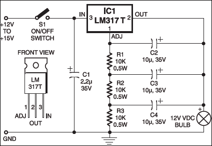
A 12-15V, 1A DC supply is connected to the input pin of the IC. A 12V, 10W bulb and a combination of resistors and capacitors are connected between the output pin and ADJ pin of the IC as shown in the figure. The IC is provided with an aluminium heat-sink to dissipate the heat generated while delivering full current. Since the IC has an inbuilt switch-on current limiter, it extends the bulb life.
For the shown values of resistors and capacitors, the bulb flashes at approximately 4 cycles per second. The number of flashes depends on the charge-discharge time of the capacitors. Different values of resistors and capacitors can be used to increase or decrease the number of flashes.
Applications
Common uses of flashing beacons include:
- Obstructions in or near the roadway, mid-block crosswalks, intersections where additional warning is needed,
- Supplement to certain warning and regulatory signs
- Speed limit, either fixed or variable intersection control
- Stop sign supplement
The article was first published in November 2002 and has recently been updated.