


 During development, testing and maintenance of digital and analogue electronic circuits and embedded systems, there is a need for TTL and CMOS signals produced by stable frequency sources. These sources are also useful for fast checking of oscilloscopes, probes, multimeters, frequency metres and other measurement equipment. This Four Frequencies Generator circuit produces fixed frequencies of 4MHz, 6MHz, 10MHz and adjustable square-wave with variable frequencies from around 10Hz to more than 100kHz.
Circuit and working
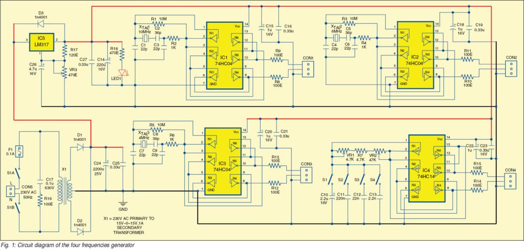
Fig. 1 shows the circuit of the four frequencies reference source. It is built with three 74C04 hex inverter ICs (IC1, IC2 and IC3) and one 74C14 hex inverter schmitt trigger IC (IC4). Each of the four blocks of the circuit in Fig. 1 produces a forward and inverted buffered signal.
IC1 uses crystal XTAL1 to produce the signal with a frequency of 10MHz. The produced output signal and inverted signal are available on connector CON1. Values of capacitors C1, C2 and C3 depend on the parameters of crystal XTAL1 and IC1.
IC2 uses crystal XTAL2 to produce the signal with a frequency of 6MHz. The produced output signal and inverted signal are available on connector CON2.
IC3 uses crystal XTAL3 to produce the signal with a frequency of 4MHz. The produced output signal and inverted signal are available on connector CON3.
As a rule of thumb, R2=reactance of C3 for IC1. Same goes for IC2 and IC3.
IC4 and associated components generate square wave with frequency from around 10Hz to more than 100kHz. Frequency ranges are selected with switches S1, S2, S3 and S4.
Potmeters VR1 and VR2 are used to adjust frequency. VR1 is for more accurate adjustment of frequency and VR2 for coarse adjustment of the frequency. The produced output signal and inverted signal are available on connector CON4. The frequency can be calculated according to the relationship given in the datasheet of IC4.
Power supply for the oscillators should be regulated; this is done by adjustable regulator LM317. Trimmer potentiometer VR3 is used to adjust the power supply to 5V.
Construction and testing
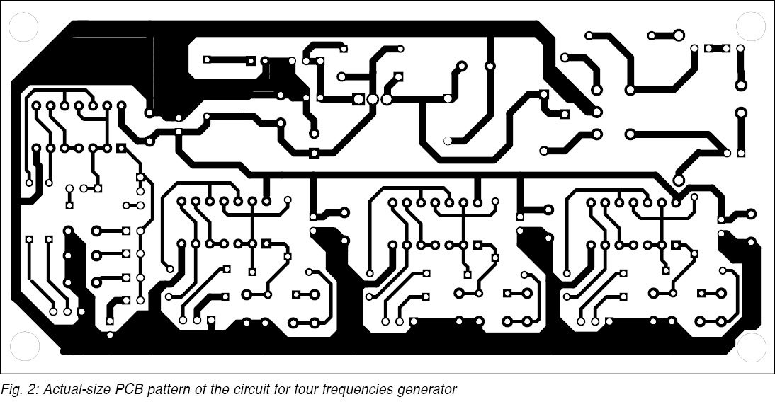
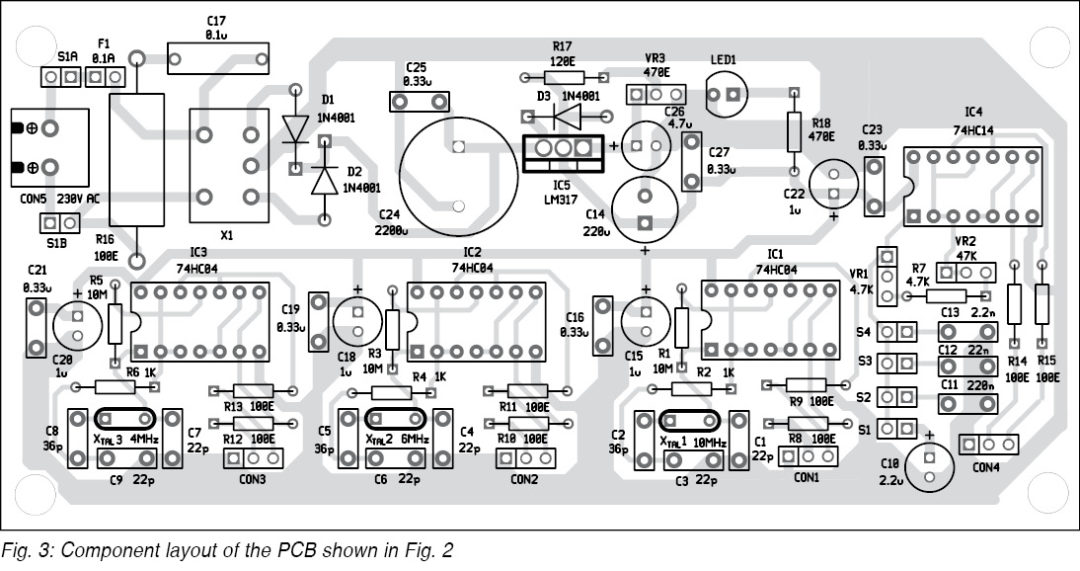
An actual-size, single-side PCB for the four frequencies generator is shown in Fig. 2 and its component layout in Fig. 3.
Download PCB and component layout PDFs: click here
Petre Tzv Petrov was a researcher and assistant professor at Technical University of Sofia (Bulgaria) and an expert-lecturer in OFPPT (Casablance), Kingdom of Morocco. Now he is working as an electronics engineer in the private sector in Bulgaria.
I had selected this for 12 th std project.I thought it is easy,but output is not coming.somethimg wrong with ckt diagram??? Plzz help.
Hi! Thank you or the question. Please try with unbuffered CMOS inverters as 74HCU04 and CD4069U and similar! It should be easier to oscilate. Please see the datacheets. Regards.
just want to start working on the project i hope all the components are readily available and i would love to know the cost implication
Excuse me, someone has already done the simulation of the circuit in the proteus program could you help me.
Bro, suggest bash shell and perl free courses.
For Bash terminal, please refer to this tutorial.
For Shell Scripting, please refer to this tutorial.
For Perl, please refer to this article.