


 Presented here is a simple humidity controller and indicator. In industries such as textile, the change in moisture content has a direct impact on the properties of fabric, such as tensile strength, elasticity, fibre diameter and friction. Therefore the process is executed within a permissible humidity environment only.
Depending on the type of fabric and the process being undertaken, the requirement of particular humidity level varies. Cotton and linen have to be processed at very high relative humidity (RH) levels of around 70-80 per cent, since they are very brittle. Wool requires RH levels of around 65 per cent. Silk needs to be processed between 65 and 70 per cent. With this circuit, you can not only monitor humidity levels between 30 and 90 per cent RH but also control it.
Circuit and working
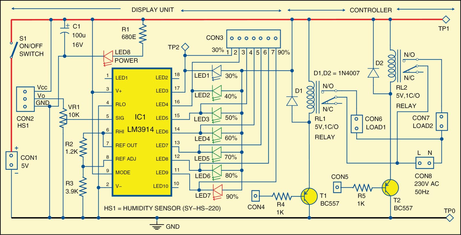
The circuit diagram of the humidity controller and indicator is shown in Fig. 1. Humidity sensor SY-HS-220 is used for sensing humidity levels and LM3914 dot/bar display driver to drive the LEDs (LED1 through LED7) corresponding to sensed humidity levels. The LEDs indicate the humidity level from 30 per cent RH to 90 per cent RH, as shown in the circuit.

Transistors T1 and T2 are relay drivers through which electrical devices can be switched on or off.
Humidity sensor (SY-HS-220)
Humidity sensors are gaining popularity in the field of measurement and control technology. The sensors for measuring water vapours as RH can be classified by the transduction scheme that they use to convert water vapour concentration into an electrical signal, viz, capacitive, resistive (DC resistance or AC impedance) and piezo-resistive.
The SY-HS-220 series humidity sensor is based on capacitive technology. This sensor module converts the RH directly into equivalent millivolts analogue output. The driver circuit is in-built in the sensor assembly (see Fig. 2). The rated voltage is 5V DC. Its operating temperature range is 0-60°C and humidity is 30-90 per cent RH. Its standard output at 25°C and 60 per cent RH is 1980mV DC.
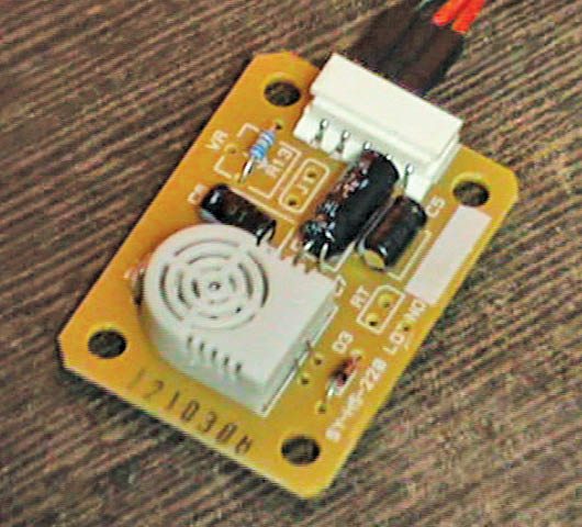
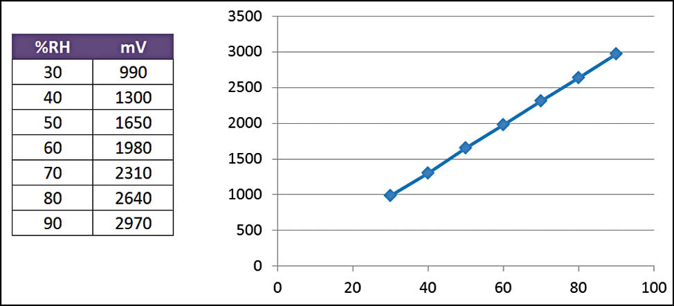
Fig. 3 shows the millivolts output reading corresponding to RH. The output of humidity sensor HS1 is connected to analogue input pin 5 of LM3914 through preset of 10-kilo-ohm (VR1).
Dot/bar display driver (LM3914).The LM3914 is an 18-pin DIP package IC that accepts analogue signals at its input pin 5 and drives 10 LEDs, providing a linear analogue display. Pin 9 is the mode-select input control for bar- or dot-mode operation. LM3914 works in bar mode when pin 9 is connected directly to pin 3 and pulled to +5V supply.
 At any point of time, if all LEDs (LED1 through LED7) glow, it indicates that the humidity level is 90 per cent RH and if only LED1 glows, it indicates that humidity is at 30 per cent RH. The number of glowing LEDs increases with increase in humidity level as shown in Fig. 1.
Before using this circuit, humidity level is first calibrated using preset VR1. You may refer to a standard humidity meter to calibrate it. For example, if a standard humidity meter shows 40 per cent RH, LED1 and LED2 should glow. If not, vary VR1 till LED1 and LED2 glow. Once calibration is done, you should not touch the preset again. Thus, if humidity level is 50 per cent, you should see LED1, LED2 and LED3 glowing.
T1 and T2 are pnp transistors for controlling two electrical devices through relays RL1 and RL2. You can trigger these relays at the desired humidity level by connecting their bases to the corresponding pins of IC1. All pins are terminated at CON3 for ease of connection. Note that RL2 can be used to stop the current process when predetermined humidity level is reached.
Construction and testing
A single-side PCB for the humidity controller and indicator is shown in Fig. 4 and its component layout in Fig. 5. Assemble the components on the PCB. Before switching on the circuit, check proper connections, especially correct polarity of the power supply at CON1. Normally, you will find humidity sensor module with five pins. You need to use only three pins (Vcc, Vo and GND) of this module, which are to be connected at CON2 in this circuit.
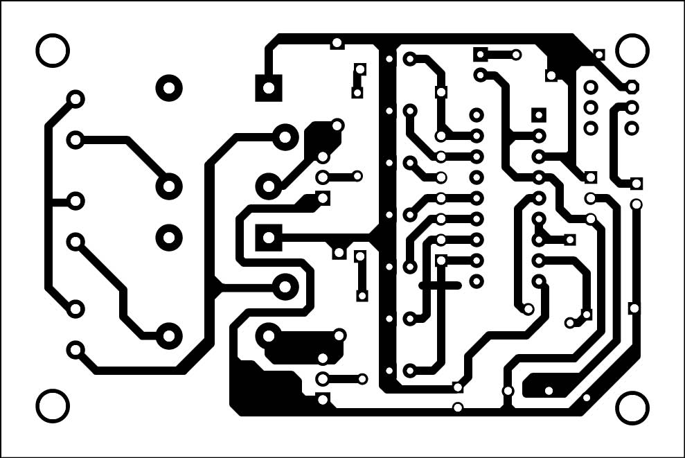
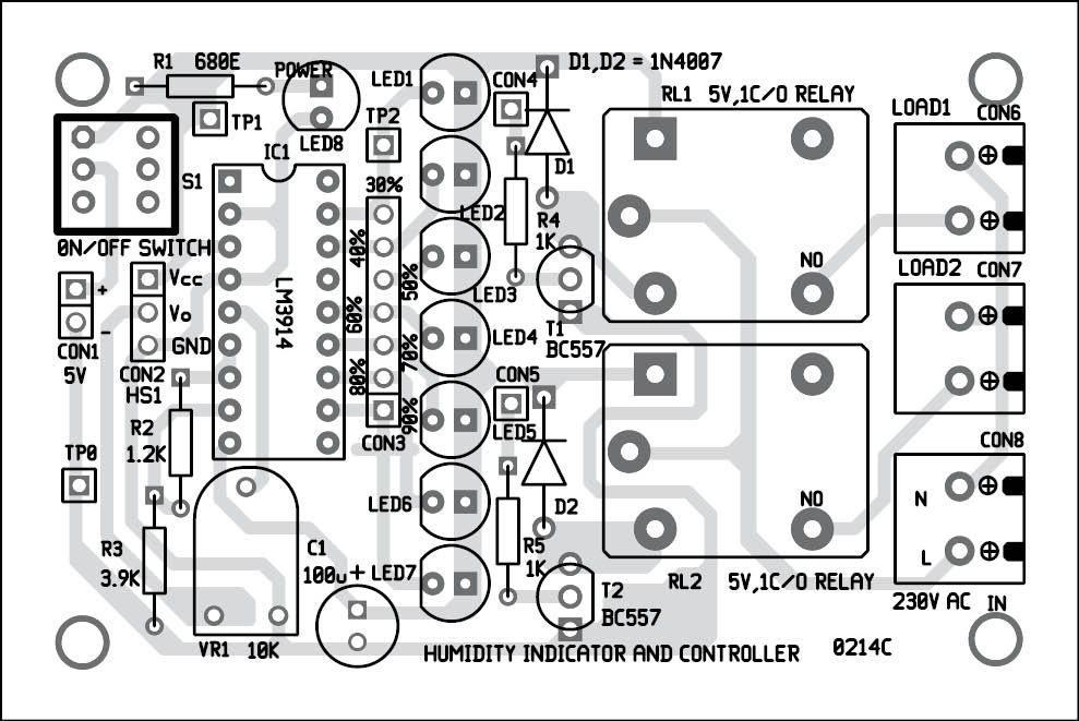
Download PCB and component layout PDFs: click here
When the circuit is turned on, vary VR1 till all the LEDs glow, to check if they are working well along with the driver.
For troubleshooting, you can refer the test points given in the table. Now, calibrate the circuit using a standard humidity meter as explained earlier. For manual testing, you can blow air from your mouth on the humidity sensor (HS1) and observe the LEDs glowing. The number of glowing LEDs depends on the moisture content in your breath.
The author is a B.Tech in electronics and communications engineering from Punjab Technical University.
can you please give me the detail about con2
hey can we connect with icl 7107 instead of lm3914 to see the output on 7 segment display?
can we connect with icl 7107 instead of lm3914 to see the output on 7 segment display?
how can we use here humidity sensor SY-HS 220 instead of SY-HS 220?
What is difference in both?