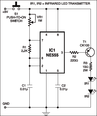
 Presented here is a infrared remote controlled timer circuit. The circuit comprises two sections, namely, the transmitter section and the receiver section. Fig. 1 shows the IR transmitter section. The astable multivibrator NE555 (IC1) is used to generate a 10kHz modulated IR signal. The output of IC1 is connected to the base of pnp transistor T1 via resistor R2. Two infrared LEDs (IR1 and IR2) are connected in series between the collector (via resistor R3) and ground. When switch S1 is pressed, the IR LEDs transmit the modulated IR signal of 10-11 kHz. This frequency can be changed with the help of VR1 potmeter.
Infrared Remote Controlled Timer Circuit

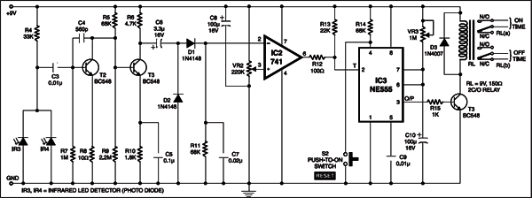
In the receiver section shown in Fig. 2, two photodiodes (IR3 and IR4) receive the IR signal transmitted by the IR transmitter. Transistors T2 and T3 amplify the weak signal. The amplified signal is filtered by capacitors C6 and C7. The amplified and filtered signal is now fed to the inverting input pin 2 of op-amp IC2 (IC 741). The output of IC2 is further connected to trigger pin 2 of timer NE555 (IC3) that is used as a monostable multivibrator whose frequency may be varied with the help of potmeter VR3.

Circuit operation
When switch S1 of the transmitter is pressed, the modulated IR rays are generated, which are received by photodiodes in the receiver section and amplified by the amplifier circuit. The output of op-amp goes low to trigger the monostable. Then high output at pin 3 of IC3 activates the two changeover relay RL via transistor T3 (BC548) for a preset time.
The on/off time can be set in the timer with the help of VR3 and C10. Switch S2 is used to reset the monostable. If you want to turn the appliance on for a preset time, connect the appliance via relay RL(a). On the other hand, if you want to turn the appliance off for a preset time, connect the appliance via relay RL(b). The timer can be reset by pressing reset switch S2. The circuit works up to 3 metres without using any focusing lens. However, you can increase the operating range by using focusing lens.
The article was first published in May 2003 and has been recently updated.


Please can you tell me how to connect the relay to the appliances and to the mains AC supply.
Mail me at [email protected]
please send video related to this project
please can you send components sheet or any extra details about the project.
that will help me as am planning to do it for project for my final year for diploma certificate.
email me [email protected] thanks in advance.
please can you send components sheet or any extra details about the project.
please send video related to this project
email me [email protected] thanks in advance.
Very thank!