


 This IoT-based project monitors soil moisture, temperature, and humidity levels near plants and light intensity near the control station. It turns on water solenoid valve when moisture level goes below the threshold level. Its vibration sensor detects movement or any other unwanted activity of animals and rodents near the plantation area.
The project is equally suitable for indoor plants in buildings, greenhouse farming, and for regular farming. Adafruit IoT platform is used to monitor various sensors’ status online.
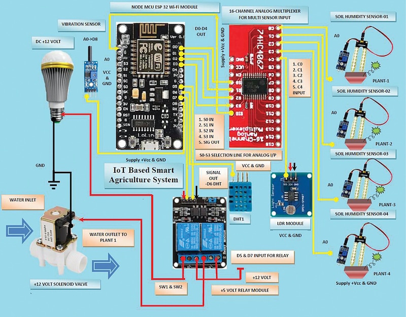
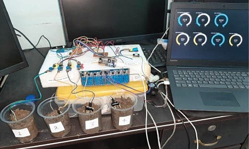
Block diagram of the low-cost smart agriculture system is shown in Fig. 1. The author’s prototype of the project is shown in Fig. 2 while its circuit diagram is shown in Fig. 3.
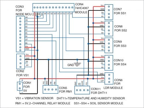
Circuit and working
The heart of the IoT system is the NodeMCU ESP-32 8266 Wi-Fi module. It is used to transmit the signals collected from various sensors to the users through a computer network. The sensors include four soil moisture sensors (SS1 through SS4), a light-dependent resistor (LDR), a vibration sensor (VS1), and a temperature and humidity sensor (DHT11).
If soil moisture or humidity level near any plant(s) goes below the threshold level (as per the program), the controller in NodeMCU switches on the solenoid valve through the relay module (RM1) and water starts flowing.
The LDR module is used to sense the day and night conditions in the control room. If light intensity in the room is below the threshold level, especially during night, it turns on the light through relay module RM1.
Sensor DHT11 is connected at D6 pin of NodeMCU to monitor the temperature and humidity levels.
Vibration sensor VS1 is connected to D8 pin of NodeMCU. Any vibration near the plant(s) is registered as unwanted activity, which alerts the user through the glowing of inbuilt LED in NodeMCU board.
NodeMCU has only one analogue input (A0 pin) but we may require as many as six sensors to interface with MCU. This problem can be overcome by using 16×1 analogue/digital high-speed CMOS multiplexer 74HC4067 with NodeMCU-ESP32.
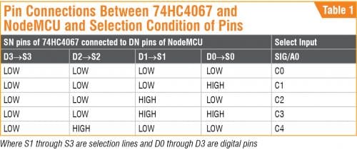
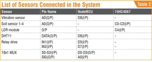
Soil moisture sensors SS1 through SS4 and one LDR sensor module are connected to input pins C0 through C4 of 74HC4067 module. The status of the five analogue inputs from these five sensors is selected using select lines S3, S2, S1, and S0. These select lines control by D3, D2, D1 and D0 pins of NodeMCU. Their connection details are listed in Table 1. The list of sensors connected in the system are shown in Table 2.
After selecting the input from 74HC4067 multiplexer module through the selection lines, a single output from the multiplexer available at pin SIG is connected to analogue input A0 of NodeMCU. The NodeMCU controller processes the input signals and turns on the light or activates the solenoid and connects the signals to the Internet.
The DHT11 sensor’s data output is connected to D6 pin of NodeMCU for detection of temperature and humidity.
To control the AC-voltage-operated lights and solenoid valve for water supply to plants, D7 and D5 pins of NodeMCU are connected to input pins IN2 and IN1 of the relay module, respectively.
Software
Arduino IDE is used for programming the NodeMCU board. Connect the NodeMCU to PC/laptop and select proper COM port and board name from Tools menu of the Arduino IDE. The board name used in this project is shown in Fig. 4.

Upload the source code Program_11973.ino to the Arduino board by clicking on the Upload button. Before compiling and uploading the source code, do not forget to include ESP8266WiFi.h, DHT11.h, Adafruit, and MQTT libraries from Library Manager.
NodeMCU Wi-Fi is connected to Adafruit.io open source cloud service to provide real-time data online. Message queue telemetry transport (MQTT) is a protocol for device communication that Adafruit.io supports.
Steps to organise the dashboard on Adafruit.io IoT platform:
- Open https://io.adafruit.com website. Create an account with a unique username. Note down this username as it will be used in Arduino code (Program_11973.ino) later.
- Generate a key and note down this key. This is a long, unique identifier that you use to authenticate any device using your account. You get one key per account, but you can revoke and regenerate your key any time.
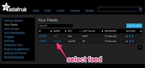
- After creating an account, you need to manage your feeds for publishing on the dashboard as shown in Fig. 5. (Feeds is basically a set of data that you can read or write, as specified in the program, as per your application.)
In this project, we have used four moisture sensors (MS1 through MS4), and a temperature sensor (tmp). So, as an example, if this program used the following in the code, then it would require to create each feed as MS1 through MS4, tmp, LHT, etc to manage on dashboard:
Adafruit_MQTT_Publish photocel3 = Adafruit_MQTT_Publish(&mqtt, AIO_USERNAME “/feeds/MS1”);
Adafruit_MQTT_Publish photocel4 = Adafruit_MQTT_Publish(&mqtt, AIO_USERNAME “/feeds/MS2”);
Adafruit_MQTT_Publish photocel5 = Adafruit_MQTT_Publish(&mqtt, AIO_USERNAME “/feeds/MS3”);
Adafruit_MQTT_Publish photocel6 = Adafruit_MQTT_Publish(&mqtt, AIO_USERNAME “/feeds/MS4”);
Adafruit_MQTT_Publish photocel1 = Adafruit_MQTT_Publish(&mqtt, AIO_USERNAME “/feeds/tmp”);
Adafruit_MQTT_Publish photocel2 = Adafruit_MQTT_Publish(&mqtt, AIO_USERNAME “/feeds/hum”);
Adafruit_MQTT_Publish photocel7 = Adafruit_MQTT_Publish(&mqtt, AIO_USERNAME “/feeds/LHT”);
You need to add all feeds in Adafruit IO to display live data from sensors on dashboard as shown in Table 3.

More details regarding configuration with Adafruit IoT and Arduino are given in ‘Configurations with Adafruit & Arduino’ document file in the source code folder.
Now open PROGRAM_11973.ino source code, include all your own Wi-Fi credentials including SSID, passwords, username, and key as shown below.
#define WLAN_SSID “Samsungi” //*Your WIFI NAME SSIDCHANGE IT(1)
#define WLAN_PASS “abcd123456” // Your WIFI password CHANGE IT(2)
#define AIO_SERVER “io.adafruit.com” //Adafruit Server
#define AIO_SERVERPORT 1883
#define AIO_USERNAME “jitendra41085” // Adafruit Username CHANGE IT (3)
#define AIO_KEY “859813f4cb144ee5b0f9e124a239a3f4” // adafruit Auth KeyCHANGE IT (4)
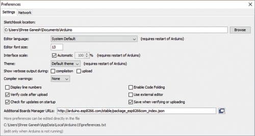
Next, change the software configuration by adding
http://arduino.esp8266.com/stable/package_esp8266com_ index.json under File/Preferences in Arduino IDE as shown in Fig. 6. Now you can save the code, compile it again, and upload it to NodeMCU board.
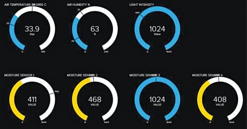
After making all the circuit connections, switch on NodeMCU board and open the Adafruit IoT dashboard. You will see something as per Fig. 7.
Download Source Code: Click Here
Jitendra Jangir is training officer (Electronics) at National Skill Training Institute (W), Patna, Bihar
V.K. Shukla is retired as director at Directorate General of Training, Ministry of Skill Development and Entrepreneurship, government of India
sir learn small and low cost circuit diagram
kindly help to us
sir hobby ckt also