


As the sources of conventional energy deplete day by day, resorting to alternative sources of energy like solar and wind energy has become need of the hour. Solar-powered lighting systems are already available in rural as well as urban areas. These include solar lanterns, solar home lighting systems, solar streetlights, solar garden lights and solar power packs. All of them consist of four components: solar photovoltaic module, rechargeable battery, solar charge controller and load.
In the solar-powered lighting system, the solar charge controller plays an important role as the system’s overall success depends mainly on it. It is considered as an indispensable link between the solar panel, battery and load.
The microcontroller based solar charger controller described here has the following features:

- Automatic dusk-to-dawn operation of the load.
- Built-in digital voltmeter (0V-20V range)
- Parallel- or shunt-type regulation
- Overcharge protection
- System status display on LCD
- Deep-discharge protection
- Low battery lock
- Charging current changes to ‘pulsed’ at full charge
- Low current consumption
- Highly efficient design based on microcontroller
- Suitable for 10-40W solar panels for 10A load
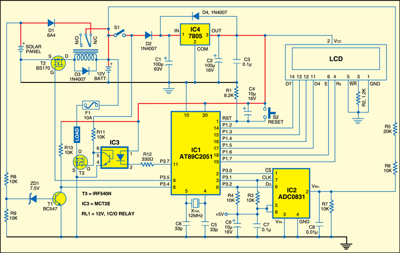
The circuit of the solar charge controller is shown in Fig. 1. It comprises the microcontroller AT89C2051, the serial analogue-to-digital converter ADC0831, the optocoupler MCT2E, the regulator 7805, the MOSFETs BS170 and IRF540N, the transistor BC547, the LCD, and a few discrete components. Component description is given below.
Microcontroller
Microcontroller AT89C2051 is the heart of the circuit. It is a low-voltage, high-performance, 8-bit microcontroller that features 2 kB of Flash, 128 bytes of RAM, 15 input/ output (I/O) lines, two 16-bit timers/ counters, a five-vector two-level interrupt architecture, a full-duplex serial port, a precision analogue comparator, on-chip oscillator and clock circuitry. A 12MHz crystal is used for providing the basic clock frequency. All I/O pins are reset to ‘1’ as soon as RST pin goes high. Holding RST pin high for two machine cycles, while the oscillator is running, resets the device. Power-on reset is derived from resistor R1 and capacitor C4. Switch S2 is used for manual reset.
Serial ADC
The microcontroller monitors the battery voltage with the help of an analogue-to-digital converter. The ADC0831 is an 8-bit successive approximation analogueto- digital converter with a serial I/O and very low conversion time of typically 32 μs. The differential analogue voltage input allows increase of the common-mode rejection and offsetting of the analogue zero input voltage. In addition, the voltage reference input can be adjusted to allow encoding of any smaller analogue voltage span to the full eight bits of resolution. It is available in an 8-pin PDIP package and can be interfaced to the microcontroller with only three wires.
LCD module
The system status and battery voltage are displayed on an LCD based on HD44780 controller. The backlight feature of the LCD makes it readable even in low light conditions. The LCD is used here in 4-bit mode to save the microcontroller’s port pins. Usually the 8-bit mode of interfacing with a microcontroller requires eleven pins, but in 4-bit mode the LCD can be interfaced to the microcontroller using only seven pins.
Solar panel
The solar panel used here is meant to charge a 12V battery and the wattage can range from 10 to 40 watts. The peak unloaded voltage output of the solar panel will be around 19 volts. Higher-wattage panels can be used with some modifications to the controller unit.
Rechargeable battery
The solar energy is converted into electrical energy and stored in a 12V lead-acid battery. The ampere-hour capacity ranges from 5 Ah to 100 Ah.
Dusk-to-dawn sensor
Normally, in a solar-photovoltaic-based installation— for example, solar home lighting system, solar lantern or solar streetlight— the load (the light) is switched on at dusk (evening) and switched off at dawn (morning). During daytime, the load is disconnected from the battery and the battery is recharged withn current from the solar panel. The microcontroller needs to know the presence of the solar panel voltage to decide whether the load is to be connected to or disconnected from the battery, or whether the battery should be in charging mode or discharging mode. A simple sensor circuit is built using a potential divider formed around resistors R8 and R9, zener diode ZD1 and transistor T1 for the presence of panel voltage.
Charge control
Relay RL1 connects the solar panel to the battery through diode D1. Under normal conditions, it allows the charging current from the panel to flow into the battery. When the battery is at full charge (14.0V), the charging current becomes ‘pulsed.’ To keep the overall current consumption of the solar controller low, normally closed (N/C) contacts of the relay are used and the relay is normally in deenergised state.
Load control
One terminal of the load is connected to the battery through fuse F1 and another terminal of the load to an n-channel power MOSFET T3. MOFETs are voltage driven devices that require virtually no drive current. The load current should be limited to 10A. One additional MOSFET is connected in parallel for more than 10A load current.
Circuit description
Basically, there are two methods of controlling the charging current: series regulation and parallel (shunt) regulation. A series regulator is inserted between the solar panel and the battery. The series type of regulation ‘wastes’ a lot of energy while charging the battery as the control circuitry is always
active and series regulator requires the input voltage to be 3-4 volts higher than the output voltage. The current and voltage output of a solar panel is governed by the angle of incidence of light, which keeps varying.
Parallel regulation is preferred in solar field. In parallel regulation, the control circuitry allows the charging current (even in mA) to flow into the battery and stop charging once the battery is fully charged. At this stage, the charging current is wasted by converting into heat (current is passed through low-value, high-wattage resistor); this part of the regulation dissipates a lot of heat.
In this project, we have used parallel regulation technique but instead of wasting the charging current as heat, we have made it pulsed and applied to the battery to keep the battery topped-up.
After power-on, the microcontroller reads the battery voltage with the help of the ADC and displays the values on the LCD. It monitors the input signal from the dusk-to-dawn sensor and activates the load or charging relay RL1 accordingly. The digital voltmeter works up to 20V. As Vref of the ADC is connected to VCC (5V), the input voltage to the ADC cannot exceed +5V. A potential divider is used at pin 2 of the ADC (IC2) using resistors R5, R6 and R7 to scale down the voltage from 0V-20V to 0V-05V. The ADC output is multiplied four times and displayed on the LCD as battery voltage.
When the solar panel voltage is present, the dusk-to-dawn sensor provides a signal to the microcontroller, which then displays ‘charging’ message on the LCD. During charging, the battery voltage is continuously monitored. When the voltage reaches 14.0V, the microcontroller interrupts the charging current by energising the relay, which is connected to MOSFET BS170 (T2), and starts a 5-minute timer. During this stage, the LCD shows “battery full.”
After five minutes, the relay reconnects the panel to the battery. This way, the charging current is pulsed at the intervals of five minutes and the cycle repeats until the panel voltage is present.
When the panel voltage falls below the zener diode (ZD1) voltage of the dusk-to-dawn sensor, the microcontroller senses this and activates the load by switching on MOSFET T3 via optocoupler IC3 and “load on” message is displayed.
In this mode, the microcontroller monitors for low battery. When the battery voltage drops below 10 volts, the microcontroller turns off the load by switching off MOSFET T3 and “battery low—load off” message is displayed.
Normally, when the load is switched off, the battery voltage tends to rise back and the load oscillates between ‘on’ and ‘off’ states. To avoid this, the microcontroller employs a hysteresis control by entering into a ‘lock’ mode during low-battery state and comes out of the lock mode when the dusk-to dawn sensor receives the panel voltage (the next morning). During lock mode, the microcontroller keeps converting the ADC value and displays the battery voltage on the LCD.
Construction and testing
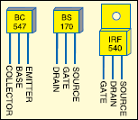
Pin configurations of transistor BC547, MOSFET BS170 and MOSFET IRF540 are shown in Fig.2. An actual-size, single-side PCB for the microcontroller-based solar charger is shown in Fig.3(View as PDF) and its component layout in Fig.4(View as PDF). Wire the circuit on the PCB. Prior to inserting the programmed microcontroller into the PCB, check for soldering mistakes like shorts, and for proper connections using a multimeter. Mount power MOSFET IRF540 on a suitable heat-sink. Before switching on the controller unit, connect the leads of the battery, load and solar panel at appropriate places on the board.
Download PCB and component layout PDFs (Fig. 3, 4): click here
Switch on the unit and the message “Solar Charge Controller–EFY” is displayed on the LCD for two seconds. The system status messages are displayed on line 1 of the LCD and the battery voltage is displayed on line 2.
A small graphic representing the battery status is also displayed on line 2 of the LCD.
EFY note: If the unit is switched on without the solar panel connected, the “Battery Low—Load Off” message is displayed irrespective of the battery voltage. The display changes to “charging” as soon as the panel is connected.
2. There will be slight variation in the voltage displayed because of the tolerance levels of potential-divider resistors in the ADC section and Vref of the ADC being directly connected to VCC (the output of 7805 has an accuracy of 2-5 per cent) instead of dedicated temperature-compensated voltage reference.
Software
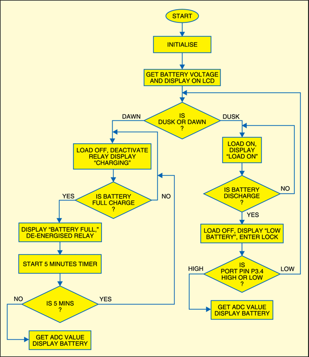
The source program for the project is written in Assembly language and assembled using Metalink’s ASM51 assembler, which is freely available on the Internet for download. It is well commented for easy understanding and works as per the flow-chart shown in Fig.5. The hex file ‘solar.hex’ is to be burnt into the microcontroller.
i need to know the cost of kit for micro controller based solar charger
I make this project display show in LCD but i attached solar panel don’t show charging status on LCD any buddy help me for this issue. Thank you
Please make complete connections and then only you should attach your solar panel in the circuit. Some people faced problems because of incomplete connection or mcu is not programmed correctly.
Can we use other microcontroller of atmega????
You cannot replace directly with Atmega, you need to change the code.
is it double layer pcb which is attached ? if not so where is the D1 and relay in this circuit
Hello,
this project is interesting and thanks for it
i am doing similar project but i am using PWM to control the charging the battery
guys any one know where i can find a circuit that used PWM to charge a battery
Yes, please refer to Photovoltaic battery charger from this link: https://www.electronicsforu.com/electronics-projects/photovoltaic-battery-charge-controller
I have make the circuit in proteus and burn the hex file in the controller. But the LCD Showing garbage.. please help
Hello
Thank you for your excellent site and topics that are of great help for me and most of those who read electronic
But we have fault in the circuit schematic and pcb is part of relay, for example, are not correct in pcb and we dont have D1 in pcb
Please input the correct pcb
Thanks
Same problem need help
Where is the D1 and RL1 in this attached pcb ? how connect ?
Is it complete PCB?
hello there,
can anyone help me with the correct PCB? is the schematic is correct? then where to connect solar panel’s negative, D1 and relay? actually after connecting solar panel’s negative, D1 (one pin on PCB and other with RL1 thru a hookup wire) and relay as per PCB, Relay do get operated but there is NO ground given to negative of solar panel. The status message on the LCD (line 1) “BAT.LOW-LOAD OFF” doesn’t go and never comes on “Charging..” status rather it do show the Battery Voltage. Someone please help me on this issue. Thank you.
We have not received any complaints on the PCB as well as schematic so far. Diode D1 is not shown on the PCB because it has to be connected externally. The negative terminal of solar panel should be connected to any ground rail on the PCB. Make sure transistors T1 and T2 and ADC chip are working properly. Check the battery level is above 10V. If all these things are working well and as per explained in the text, you will not get the message “BAT.LOW-LOAD-OFF” on the LCD. Sometimes the data in the MCU may get corrupted, so you may try it by re loading the program.
Hello Admin
i m facing same issue like kanu.You can tell me this issue for mcu is not programmed correctly . plz send me correct hex file for this project.i m checked all connection its perfect connected. My email [email protected]. ThnQ
The complete source code including the hex code is available here.
does this project is correctly connected because i did it twice but didnt show any display on lcd?
can this program work for 24v
Hi..is this the correct schematic for the project. While.I was going through a lot of comments on the project I have seen that there were some.problems with the Lcd, relay and Diode D1. Because i need a charge controller for my street lighting project and this fits all my requirements.
@efylab I dont know where the problem lies but the lcd is displaying garbage values….do u have the .c file of the code.
First, check the correct connections to LCD, download the hex code again from our website, burn the code into the MCU and see if you are still getting garbage values. This project was designed in Assembly language and not C language, so .c file is not available.
This is awsame ! can we use this circuit as a common lead acid battery charger ?What modification to be need for that ?
Regards
Ajitkumar
hello EFYLAB,its not generating PWM signals and Same above mentioned problem LCD displaying garbage value..please be clarify and replace it with working code please..
Can we use this project for automatic turn-off mobile Battery charger@efylab
Were i got the pcb
The PCB file is provided within the article.
@efylab may i get the protues save file for this.
hi @efylab may i get the PCB save file for this project
Hi, you can get all the PCB and component layout PDFs from here.
Hii…@efylab
where i will find source code of solar charge controller.
The source code is present at the end of the article. Please refresh to download.
yes….got it.
i have one question solar charge controller are available with positive ground or common positive and negative ground. when to use or which is the best for MPPT ?