 Over-watering and under-watering both are harmful for plants. Roots need air as well as water. If the soil is constantly saturated, air cannot reach the roots and they suffocate. Also, excess water weakens the plant and makes it susceptible to various diseases, particularly fungal attacks. Under-watering, on the other hand, is equally harmful. Plants not receiving enough water droop from the top down and leaf edges turn brown. A moisture monitor can make things better.
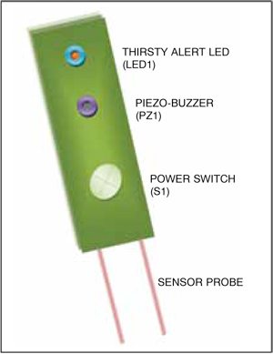
A moisture monitor provides a solution to the above problem by monitoring the moisture level of the soil and producing an audio-visual alert when the moisture goes below a preset level, indicating that the plant needs to be watered. Fig. 1 shows the proposed layout of the device.
Moisture monitor circuit and working
Fig. 2 shows the circuit of moisture monitor for plants.
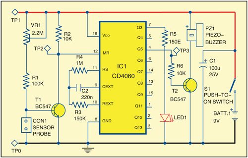
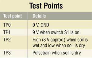
The core of the circuit is inexpensive and built around popular 14-stage ripple-carry binary counter CD4060 (IC1) and a few commonly available components. Not all the outputs of the binary counter are available externally. The frequency at pin 7 (Q3) of IC1 is actually divided by 24=16 compared to initial astable frequency. Similarly, Q4 will have half the frequency of Q3. Components R3, R4 and C2 set the clock oscillator frequency to control the flash rate of LED1 and the beeping rate of PZ1. Pulses are enabled when reset pin (pin 12) is low and disabled, or inhibited, when reset pin is high.
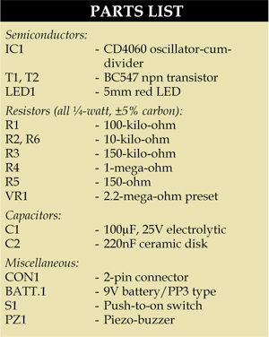
Working of the circuit is simple and straightforward. The base of transistor T1 is connected to a ‘gimmick’ potential divider comprising sensitivity control preset VR1 (2.2-mega-ohm), fixed resistor R1 and the moisture sensor probe. In standby state (soil in wet condition), IC1 is disabled because its reset pin 12 is directly tied to +9 V through resistor R2. However, when the soil is dry, transistor T1 is forward biased by VR1 and R1. This enables IC1 to oscillate. As a result, LED1 starts blinking and piezobuzzer PZ1 sounds to indicate that the plant needs water.
Moisture monitor requires a 9V supply. A PP3-size battery is recommended for compactness.
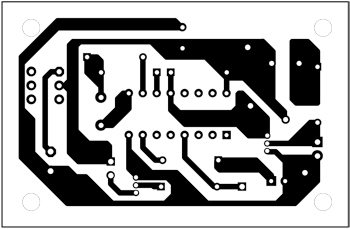
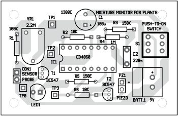
Download PCB and component layout PDFs: click here
Construction and testing
An actual-size, single-side PCB for flora caretaker is shown in Fig. 3 and its component layout in Fig. 4. After construction, enclose the whole circuit in a suitable crystalline tube or box. The moisture sensor probe can be constructed using two small metal rods (steel or copper) mounted vertically with a small gap (about 10 mm) in between them. These two metal rods must be supported by a small insulated (wooden or plastic) board. You can place one flora caretaker in each plant pot for constant monitoring of soil moisture.
The author is a freelance writer and regular contributor to EFY. He has many articles published to his credit in India and abroad.


Can you just provide me the Software Simulation of this file in Proteus please?
No, we do not use Proteus, we tested the circuit on breadboard
So sorry we do not have proteus simulation file with us right now.
Could you help me with the circuit design with the same