


A radio frequency oscillator is at the heart of all radio transmitters and receivers. It generates high frequency oscillations, which are known as carrier waves. Here’s a continuous wave (CW) multiband transmitter for transmitting. Morse code signals in the shortwave band (see Fig. 1). It is basically a variable frequency oscillator (VFO) whose frequency can be varied from 5.2 MHz to 15 MHz. The signal can be received in the shortwave band by any radio receiver. The circuit works off a 9V battery.
Multiband transmitter circuit
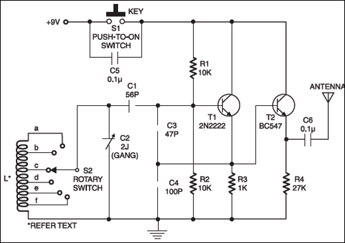
Connect the Morse key (S1) across capacitor C5 as shown in the figure. Attach a telescopic antenna (capable of transmitting over a short distance) at the output terminal.The coil and gang capacitor C2 form the tank circuit. The coil (L) has a total of 60 turns. Winding details tails are given in Fig.2. Tappings on the coil allow selection of the required band. The frequency can be varied using C2 (main tuning).
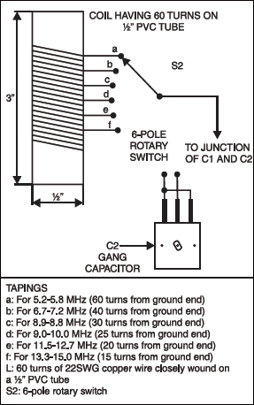
On reducing turns of the coil (using selector switch S2), the oscillator’s frequency increases because frequency is inversely proportional to inductance. Capacitor C1 couples the signal from the tank circuit to the base of transistor T1 (2N2222). Transistor T1 provides the required positive feedback for oscillation and transistor T2 (BC547) functions as the emitter follower. The output is taken from the emitter of T2.

For stable oscillations, use a polystyrene capacitor as C1. All other capacitors may be ceramic disk type. Enclose the circuit in a metal box for better shielding.
The article was first published in January 2004 and has recently been updated.
So, what value is the variable tuning gang supposed to be?
Did you ever get an answer as to the value for C2 in the shortwave transmitter?