


 This NeoPixel LED lighting based on WS2811 driver and Arduino digitally produces red, green, and blue (RGB) lights and the combinations. Originally introduced by Adafruit, the LED strips come with driver ICs that are addressable and programmable.
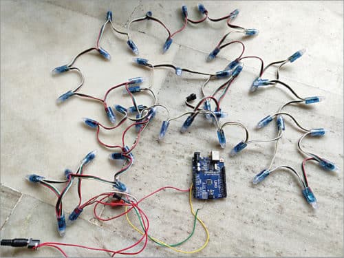
There are several types of LED strips/arrays available but we may use the one based on WS2811 driver chip. However, its equivalents WS2812, WS2812b, and WS2813 can also be used. Serial protocol bus used to address and control the LEDs can be somewhat complex and tricky as the drivers can generate quite a few lighting effects and patterns like zig zag, random, 7-segment digital clock, scrolling message displays, etc. The author’s prototype is shown in Fig. 1.
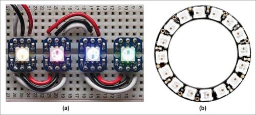
The NeoPixel LED lighting available in the market is usually costly. The use of WS2811 driver in this project helps reduce cost. NeoPixel LEDs come in a wide variety of pixel densities and form factors, besides the traditional LED strip, such as rings, matrices, and several other types of individual pixels as shown in Fig. 2.

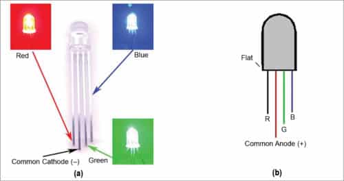
Controlling a WS2811 device via its serial control bus is not a straightforward task. It uses a combined clock and data line to ripple the instructions for each LED down the serial daisy chain bus, which runs from one pixel to the next (Fig. 3). This means the pixels can not be addressed individually. So, any change in one of the pixels would require refreshing the instructions loaded into all the pixels upstream. RGB LED’s pin diagrams are shown in Fig. 4.

Controlling NeoPixel LEDs
Generating instructions for a string of WS2811 LED drivers requires very specific and complicated timing that can make the driver code a bit tricky to write from scratch.
Fortunately, much of the hard work has already been done and there are libraries (FastLed.h, NeoPixel.h) available for LED strip drivers and applications available for Arduino, Raspberry Pi, LaunchPad, and other popular platforms. Even Assembly language driver routines are available for WS2811-based products for some microcontrollers (MCU), including Atmel’s popular 8-bit ICs, TI’s TMS430 series and Microchip’s PIC16F15xx devices.
Here, pulse width modulation (PWM) is used to control the NeoPixel LEDs. After resetting the controller of the LED chain by holding the input low for 50µs, the MCU program begins sending a stream of 24-bit colour codes (8-bit each for the R, G, and B LEDs) down the line. The first set of 24-bit RGB value is latched and displayed by the first LED pixel, which then allows the remaining bit stream to pass down the chain. The second LED pixel grabs RGB bit sequence, displays it, and so on, until the end of the chain is reached. The PWM pulses are varied to produce multiple colours with the combination of RGB LEDs.
Circuit and working
Connection diagram for the NeoPixel addressable LEDs using Arduino is shown in Fig. 5. Connect a 5V DC power supply to Arduino and the NeoPixel LED strip. Connect the +5V pin of the LED strip to the positive terminal of power supply. Do not connect 5V pin of the Arduino to the LED strip. Connect DIN and GND pins of the LED strip to digital pin 6 and GND pin of the Arduino, respectively. Make sure the GND pins of LED strip, Arduino, and 5V DC power supply are connected to each other.
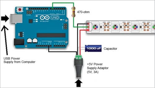
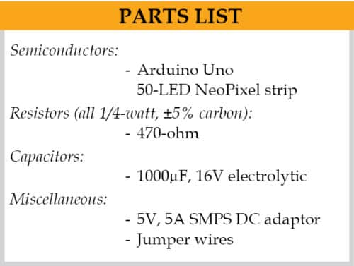
This project uses a NeoPixel compatible 50-RGB LED strip and a power supply of 5V, 5A from a DC adaptor. This is because each NeoPixel consists of three LEDs (red, green, and blue), and each LED draws a maximum current of 20mA. That means, 60mA (20mA x 3) current is required for each NeoPixel LED, as shown in Fig.3. Total current requirement for fifty LEDs would thus be 50×60mA=3000mA, or three amperes. So, the DC adaptor should have at least 3A or more current rating.
While using a DC power supply, or a large battery source, a 1000µF, 16V or higher capacitor should be added across the plus (+) and minus (-) terminals. This prevents the initial onrush of current from damaging the LEDs. Adding a 470-ohm resistor between data pins of Arduino and NeoPixel LEDs can help prevent spikes on the data line, which can damage the first LED.
Software
Circuit operation is controlled by the software program loaded into the internal memory of Arduino Uno. The program (main1.ino) is written in Arduino programming language. Arduino IDE is used to compile and upload the program.
ATmega328P on Arduino Uno board comes with a pre-programmed bootloader that allows you to upload a new code to it without using an external hardware programmer. Connect Arduino board to the PC and select the correct COM port in Arduino IDE.
Along with Arduino program/sketch (main1.ino), you also need a header file (FastLED.h) for implementing multiple lighting effects and animation. Some major functions and operations used in the program code are:
#define LED_TYPE WS2812
It is an inbuilt function of FastLED.h to declare specific type of pixel LED packs like WS2811,WS2812,WS2812b, and WS2813.
#define COLOR_ORDER GRB
In this function you need to specify the order of the colour sequence of green, red, and blue colours.
#define BRIGHTNESS 64
In this function you can vary the brightness of LEDs, whose range is from 0 to 255 levels.
#define NUM_LEDS 50
In this function you specify the number of LEDs used (50 in this project).
Header file is included in FastLed-master.zip file. Before compiling the sketch, you need to include FastLed-master.zip in the Arduino library.
Testing
After making the connections as shown in Fig. 5, upload the source code to Arduino Uno board. Connect Arduino board to 5V DC source through its USB cable by connecting to your PC/laptop. Then connect a 5V, 5A DC adaptor to the NeoPixel LED strip. You will see different LED light effects and patterns on the LED strip.
Note. While connecting a NeoPixel LED strip to any live-power source through an AC/DC adaptor, first connect the ground (-) terminal before connecting any other pin. Conversely, disconnect the ground terminal last when separating strip from the power source.
Download Source Code
Pamarthi Kanakaraja is an assistant professor (R&D cell) at K.L. University, Vaddeswaram, Guntur district, Andhra Pradesh

Hi my name is Gainfranco,I’m a beginner with Arduino/neopixel RGBW. I would like to project a lamp that uses 2 neopixel RGBW sticks. My intent is to dimmer the sticks by using 2 force sensors. Could you help me please how to dimmer the neopixel RGBS ?All suggestions are welcomed and appreciated.many thanks.Regards Gianfranco