


Presented here is a numeric display digital dice circuit. Timer IC 555 wired as an astable multivibrator produces pulses at about 48 kHz rate. These pulses are fed to pin 14 of the decade counter IC 7490. The oscillator is activated by depression of switch S1.
Numeric Display Digital Dice Circuit
Using different connections for pins 2, 3 (reset to zero inputs Ro(1) and Ro(2)) and the binary output pins 12, 9, 8 and 11 of IC 7490, various count ranges can be set. For the given circuit the count range is set as 0 to 5 by connecting QB and QC outputs to Ro(1) and Ro(2) inputs, respectively.
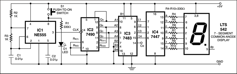
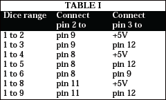
At the count of 6, QB and QC outputs of IC2 go high and counter is reset. The binary output pins of the counter IC2 are connected to corresponding input pins of 4-bit binary adder IC3 (7483) which is wired to give binary output equal to binary input+1. Thus the output of the dice ranges from 1 to 6. For obtaining other dice ranges, reset pins 2 and 3 connections may be made as per Table I.

The binary summation outputs from IC 7483 are connected to IC4 (7447) which is a BCD to 7-segment decoder/driver. The output from IC4 is connected to a 7-segment common-anode LED display (LTS542).
Circuit operation
When switch S1 is depressed, the LED (D1) glows and the number displayed at the 7-segment display changes at a rate of about 48,000 times per second. As soon as the switch is released, the last (latest) number remains on display. Thus the circuit performs the function of a random number generator with the displayed number lying within the selected (wired) range.
The article was first published in January 2007 and has recently been updated.
Even though my circuit connections are perfectly right , in the output that means in the 7-segment it is displaying ‘0’ continuously . If the input is changed output is not varying.