


If your PC overheats, it could damage its expensive components. Here’s a circuit that warns you of your PC getting heated. Today’s computers contain most of the circuitry on just a few chips and reduced power consumption is a byproduct of this LSI and VSLI approach. Some PCs still have power supplies that are capable of supplying around 200W, but few PCs actually consume power to this extent.
On the other hand, apart from some portable and small desktop computers that use the latest micro-power components, most PCs still consume significant amount of power and generate certain amount of heat.
The temperature inside the average PC starts to rise well above the ambient temperature soon after it is switched on. Some of the larger integrated circuits become quite hot and if the temperature inside the PC rises too high, these devices may not be able to dissipate heat fast enough. This, in turn, could lead to failure of devices and eventually of the PC.
Various means to combat overheating are available, ranging from simple temperature alarms to devices like temperature-activated fans to keep the microprocessor cool.
Here is a PC temperature alarm that activates an audio ‘beeper’ if the temperature inside the PC exceeds a preset threshold. This temperature is user-adjustable and can be any where between 0°C and 100°C.
PC Temperature Alarm Circuit
The unit is in the form of a small PC expansion card, which you simply need to plug into any available slot of the host PC. It is powered from the PC and consumes only about 12 mA.
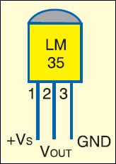
The sensor (LM35) used here provides a substantial amount of on-chip signal conditioning, including amplification, level shifting and phase inversion. As a result, it provides an output of 10 mV per degree centigrade rise in temperature. It caters to a temperature measurement range of 0°C to 100°C, which corresponds to 0V to 1V of voltage.
Circuit Operation
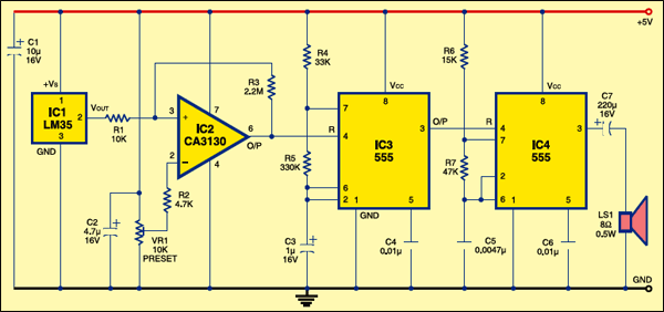
The voltage-detector stage compares the output voltage of the temperature sensor with the preset reference voltage. The output of the comparator goes high if the output potential from the sensor exceeds the reference voltage. When this happens, the voltage comparator enables a low-frequency oscillator, which, in turn, activates the audio oscillator. The output of the audio oscillator is connected to a loudspeaker (LS1), which sounds a simple ‘beep-beep’ alarm. The reference voltage determines the temperature at which the alarm is activated.
Fig. 1 shows the circuit of the PC temperature alarm and Fig. 2 shows the pin configuration of sensor LM35. IC LM35 (IC1) is an easy-to-use temperature sensor. It is basically a three-terminal device (two supply leads plus the output) that operates over a wide supply range of 4 to 20V. Tt consumes only 56 µA at 5V and generates insignificant heat. IC2 is an operational amplifier used here as a voltage comparator. VR1 provides a reference voltage that can be set anywhere from 0V to approximately 1V, which matches the output voltage range of IC1. This reference voltage is applied to the inverting input of IC2 and the output of IC1 is coupled to the non-inverting input. Consequently, the output of IC2 is low if the output of IC1 is below the reference voltage, or high if the output of IC1 exceeds the reference voltage.
Timer IC
The low-frequency oscillator IC3 is a standard 555 astable multivibrator circuit. It is gated via the reset input at pin 4, which holds output pin 3 low when IC3 is gated ‘off’ (when the output of IC2 is low). This prevents IC4 from oscillating. IC4 is another 555 astable multivibrator circuit, gated via its reset input. It has an operating frequency of approximately 2.5 kHz.
When IC3 is activated, its output provides a square wave of 1 Hz. This is used to trigger IC4, which gives an audio output of 2.5 kHz in bursts. It is connected to loudspeaker LS1 to generate alarm. The alarm circuit can be fitted into any spare expansion slot of the PC, but be careful to fit it the right way round. Before setting VR1 to a suitable threshold temperature, decide what that temperature should be. The technical specification in your computer’s manual might be of help here. If we assume that the room temperature will not normally exceed 25°C, the temperature of the interior of the computer would be up to 35°C.
Testing
Unless you have good reason to use a different threshold temperature, VR1 should be set for a wiper potential of 350 mV. Trial-and-error method can be used in the absence of test equipment to enable VR1, but it would be a bit time-consuming. There is a slight complication in that the computer’s outer casing must be at least partially removed to provide access to VR1. Once VR1 has been adjusted, the outer casing must be put back into place so that the interior of the computer can warm up in the normal way. You must therefore allow time for the temperature inside the computer to rise back to its normal operating level each time VR1 is readjusted.
The article was first published in September 2007 and has recently been updated.
please can you explain disadvantages of PC TEMPERATURE ALARM