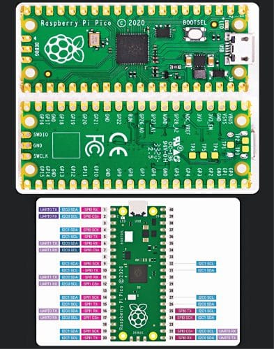
 Raspberry Pi’s first board based on a single microcontroller chip, the Raspberry Pi Pico (Fig. 1), is designed for physical computing—similar in concept to an Arduino—ratherthan perform the role of a general-purpose computer (like the others in the range). The Raspberry Pi Pico has 264kB RAM and 2MB flash memory, and it is programmable in MicroPython, CircuitPython, and C (https://en.wikipedia.org/wiki/Raspberry_Pi).
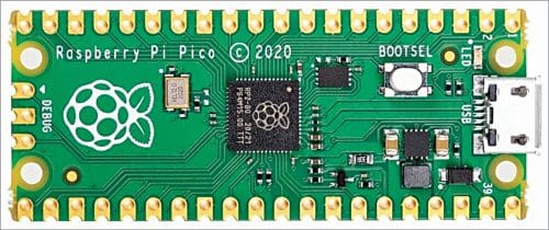
The purpose of this article is to introduce Raspberry Pi Pico (RPi Pico), which operates at 133MHz with dual cores. Because it can run MicroPython, even a novice can start coding in a short amount of time. So, here is a project that can be done easily.

However, before jumping into the experiment/project, it would be a good idea to get acquainted with the RPi Pico microcontroller board. The following links would help you to ensure a great start:
Firmware for Raspberry Pi Pico can be gathered from this link
You can download Thonny – Python IDE for beginners
This link helps you learn how to program Raspberry Pi Pico using MicroPython
Making a noise generator
The Raspberry Pi Pico based noise generator project described here is in fact a simple tone generator setup realised with the help of a few external parts. Its schematic diagram is shown in Fig. 2.
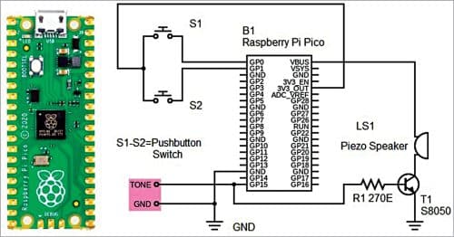
As you can see, the setup delivers an analogue output through GP15 of Raspberry Pi Pico to drive a piezo speaker. The pushbutton switches S1 and S2 are wired to GP0 and GP1 to control the tone generation.
The element used here for sound is not a common piezo buzzer; it is a piezo speaker that is also called ‘motherboard speaker.’ This piezo speaker (Fig. 3) is usually employed to obtain beep sound from computer motherboards, alarm systems, and other electronic devices. The tone output from the Raspberry Pi Pico board (TONE and GND) is quite low, so transistor S8050 is used to drive the 16-ohm sounder element (LS1).

The entire hardware setup can be operated from a stable 5V DC/USB power source. The simplest way is to plug the external USB power source into the onboard micro-USB connector, which will power VSYS and therefore the system from the USB 5V (VBUS).
Software
Instead of looping fast to read the value of a pushbutton switch, the microcontroller can also be notified of a change through an interrupt request (IRQ). An IRQ lets the processor be interrupted from its main loop to do a thing before returning to the task it was doing earlier.
The simplistic code prepared for the above hardware setup to control the IRQ using two buttons (S1 and S2) and then generate an analogue output to drive the sounder element is given alongside (source of inspiration). The source code (piconoisemaker.py) is listed below:
import machine
#Setup Button Input x2 (0 & 1)
ButtonA = machine.Pin(0, machine.Pin.IN,
machine.Pin.PULL_DOWN)
ButtonB = machine.Pin(1,machine.Pin.IN,
machine.Pin.PULL_DOWN)
#Setup PWM Buzzer Output x1 (15)
Buzzer = machine.PWM(machine.Pin(15))
Buzzer.duty_u16(32767) #Make it 50% duty
cycle (32767/65535)
Frequency = 1000 #Set a starting
frequency of 1kHz
def ButtonIRQHandler(pin):
global Frequency
if pin == ButtonA: #Raise the frequency
if Frequency < 2000:
Frequency += 50
elif pin == ButtonB: #Lower the
frequency
if Frequency > 100:
Frequency -= 50
#Setup the IRQ and hook it to the handler
ButtonA.irq(trigger = machine.Pin.IRQ_
RISING,
handler = ButtonIRQHandler)
ButtonB.irq(trigger = machine.Pin.IRQ_
RISING,
handler = ButtonIRQHandler)
while True:
Buzzer.freq(Frequency)
While on the subject, a PY file is a program file (or script) written in Python, which is an interpreted object-oriented programming language. It can be created and edited with a text editor but requires a Python interpreter to run. Simply go for Thonny!
Thonny IDE
Thonny comes with Python 3.7 built in, so you do not need to install Python separately. Just install Thonny in your computer and you are ready to go!
Once you have installed Thonny IDE, connect your Raspberry Pi Pico board with your computer through an appropriate USB data cable. You need to press and hold the BOOTSEL button on the Raspberry Pi Pico board (B1) while connecting it to your computer using a USB-A to micro-USB data cable.
After successfully connecting to PC, you can see your Raspberry Pi Pico as USB mass storage device.
Now you can open Thonny IDE and there will be a popup that shows some information regarding Raspberry Pi Pico. Just proceed to install the MicroPython firmware. Your Raspberry Pi Pico board is now updated with MicroPython firmware and is ready to execute Python codes.
(Actually, there is also a drag and drop way to do this. Check this link)
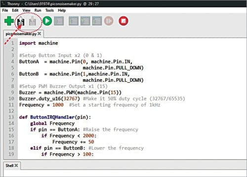
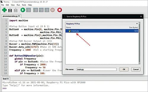
Copy-paste the above Python code in Thonny editor window (Fig. 4) and save the code before you run it. See there are two floppy disc buttons—open and save.
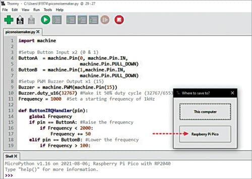
Choose Raspberry Pi Pico in the “where to save to” popup window, as shown in Fig. 5, assign a name for your Python file with an extension ‘py’ and click OK.
Once the code is saved, the green Play button on top can be used to execute the code in Raspberry Pi Pico. To stop the code’s execution, use the red Stop button.
Remember, the noise generation code should be run automatically to power the standalone Raspberry Pi Pico setup. So, when saving the code file on the Raspberry Pi Pico board, name it main.py (Fig. 6).
Awesome? Well, just do it your own way!
Testing
Testing of this project is simple if you know what you are going to do! After successful construction, just run the prototype with a USB power bank or a similar USB power source. If all goes well, the tone signal would be heard. The pushbuttons S1 and S2 can be used to increase or decrease the tone frequency.
The author has been playing with Raspberry Pi Pico a lot lately. He has written on some online channels about Raspberry Pi Pico, which is an awesome minuscule microcontroller board capable of running code to control physical hardware. Pin details of the Pico board are shown in Fig. 7.
The Raspberry Pi Pico used for this project already had headers soldered on, and the author had previously put MicroPython on it. He is using Thonny 3.3.3 (Fig. 8) on his Windows 10 (64-bit) computer.

The author’s prototype wired on the breadboard is shown in Fig. 9.

This tutorial is presented by the author for you to try and learn. You may improve the code for better application. You may even take this further into the realm of professional electronic tone generators. It is hoped you will find more interesting ways to play with audio on the Raspberry Pi Pico!
Download Source Code
T.K. Hareendran is an electronics designer, hardware beta tester, technical author, and product reviewer