


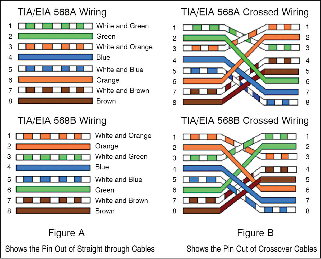
 Described here is a simple RJ45 cable tester circuit which can be used for testing the RJ45 network cables. The circuit can check both straight-through and crossover-type RJ45 network cables. This is a low-cost tester designed using easily available components. Fig. 1 shows the difference between straight-through and crossover network cables. The tester also indicates the type of cable under test with different sequences in which LEDs glow for both types of cables.
 RJ45 cable tester circuit
 RJ45 cable tester circuit
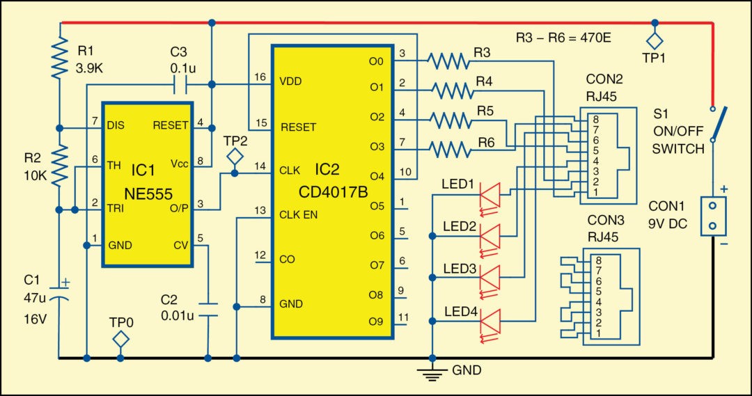
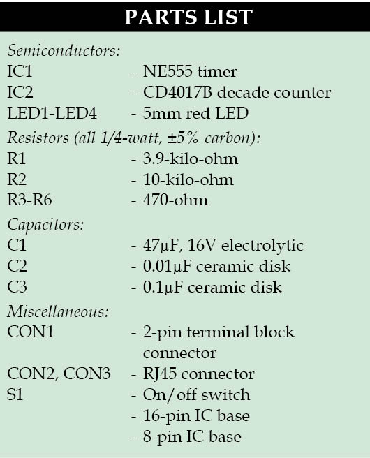
Fig. 2 shows the circuit diagram of RJ45 cable tester. The circuit makes use of easily available components such as timer NE555 (IC1), decade counter CD4017B (IC2) and a few other components. IC1 is a popular timer, wired in astable multivibrator mode generating output pulses of around 1Hz at pin 3.
Download PCB and component layout PDFs: click here
These pulses serve as a clock for decade counter IC2. The outputs O0 through O3 of IC2 go high one after another with the input pulses at pin 14. These are connected to the RJ45 socket CON2 such that a pulse is sent through one leg of each wire-pair and the return legs are connected to ground via LEDs showing the current flow in each pair. Resistors R3 through R6 are used to limit the current through each LED. Output O4 resets the counter IC2 on every fifth clock.
 For testing the RJ45 cable, connect the cable between CON2 and CON3 and switch on the power supply through switch S1.
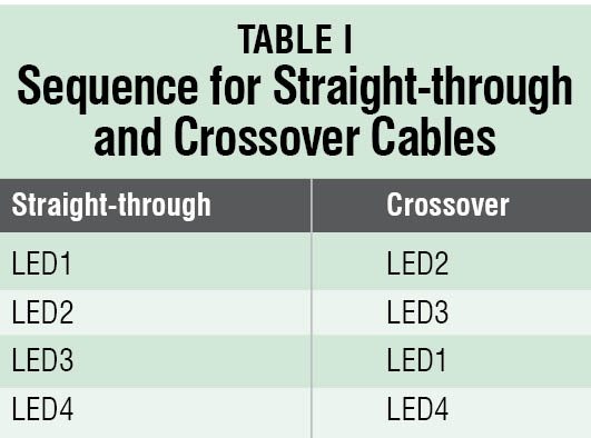
If the LEDs glow in the sequence of LED1, LED2, LED3 and LED4, the cable under test is straight-through type and is working well. Similarly, if LEDs glow in the sequence of LED2, LED3, LED1 and LED4, the cable is crossover type and is working well. Refer Table I for the sequence of LEDs.
Construction and testing
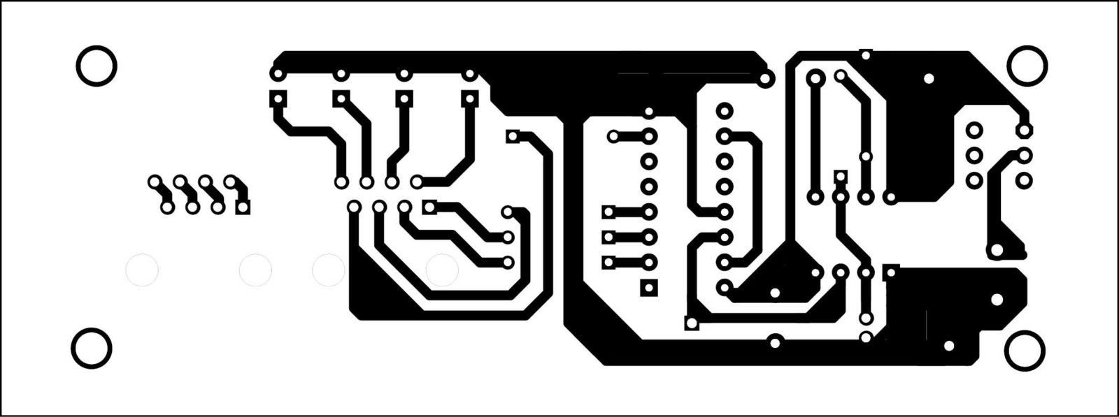
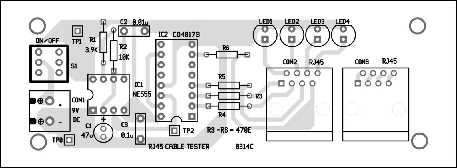
A single side PCB for RJ45 cable tester is shown in Fig. 3 and its component layout in Fig. 4. After assembling the circuit on PCB, enclose it in a suitable plastic case.
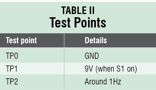
Mount all the components on the PCB and enclose it in a plastic cabinet. Make arrangements in the cabinet such that CON1, CON2, CON3, S1 and LED1 through LED4 stick out of the cabinet for proper operation. The circuit is simple and does not require much testing, but do check various voltage levels on test points corresponding to test point table.
The article was originally published in March 2014 and has been recently updated.
Hi, I have made this tester on strip board using the schematic diagram, and it worked first time.
Just to make it on PCB I printed the PDF’s and transferred figure 3 onto the copper plate by ironing it on from a copied image.
It didn’t work, I’m thinking that the image is reversed and that at least IC2 is out of sync with R3-6.
Can you please confirm if my thinking is correct.
I love the circuit, its simple and meets all my needs.
Regards,
Jim
Hello to all, I came across this little circuit and used a few spares from the projects pile and it works well. Not used the foil patton tho.
Thank you for your feedback.