


 This circuit simulates a seismic sensor to detect vibrations/sounds. It is very sensitive and can detect vibrations caused by the movement of animals or human beings. So it can be used to monitor protected areas to restrict entry of unwanted persons or animals.
The circuit uses readily available components and the design is straight forward. A standard piezo sensor is used to detect vibrations/sounds due to pressure changes. The piezo element acts as a small capacitor having a capacitance of a few nano farads. Like a capacitor, it can store charge when a potential is applied to its terminals. It discharges through VR1, when it is disturbed.
Seismic sensor circuit
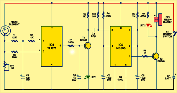
In the circuit, IC TLO71 (IC1) is wired as a differential amplifier with both its inverting and non-inverting inputs tied to the negative rail through a resistive network comprising R1, R2 and R3. Under idle conditions (as adjusted by VR1), both the inputs receive almost equal voltages, which keeps the output low.

TLO71 is a low-noise JFET input op-amp with low input bias and offset current. The BIFET technology provides fast slew rates. Capacitor C1 is provided in the circuit to keep the differential input of IC1 for better performance.
When the piezo element is disturbed (by even a slight movement), it discharges the stored charge. This alters the voltage level at the inputs of IC1 and the output momentarily swings high as indicated by green LED1. This high output is used to trigger switching transistor T1, which triggers monostable IC2. The timing period of IC2 is determined by R7 and C5. With the shown values, it will be around two minutes. The high output from IC2 activates T2 and the buzzer starts beeping along with red light indication from LED2.
Construction & testing
Assemble the circuit on a common PCB and enclose in a suitable cabinet. Connect the piezo element to the PCB using single-core shielded wire. Enclose the piezo element inside a rustproof, small aluminium box. The piezo element should be firmly glued to the enclosure facing the fine side towards the case. Fix the sensor assembly on the back side of a ceramic tile or granite tile with good adhesive. Fix the tile (or bury it in the earth) near the entrance with the sensor assembly facing downwards. Whenever a pressure change develops near the sensor, the circuit will be activated.
The article was first published in November 2007 and has recently been updated.

Sir we can’t use LM3QO4 ic in sesmic sensor?
r04-27-2023
(1.) Hi, there.
(2.) Regarding the IC TL071, which version should be used in this circuit:
(2a.) 93a59nm
(2b.) 98an7qm
(2c.) 20ale3m
(3.) New to electronics, so could you add a breadboard photo for easier reference?
(4.) Thanks.
(5.) Toodles!