


 As smart devices are increasing day by day, there is need to add smartness to the old, rugged iron box. An iron box contains a simple resistive heater and thermostat to control iron’s temperature according to the fabric. Sometimes mishandling of the iron box can cause severe fire accidents. Here is a smart method to control the iron box by switching it off and on at an appropriate time.
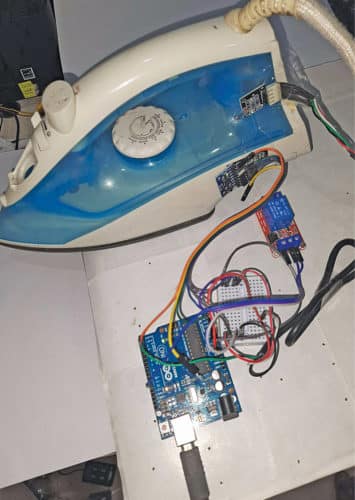
Motion and position sensors are used to detect the motion and position (vertical or horizontal) of the iron box, respectively. The iron box is switched on only when it is in motion during ironing. When it is placed in vertical position, it gets switched off. The author’s prototype wired on breadboard is shown in Fig. 1.
Circuit and working
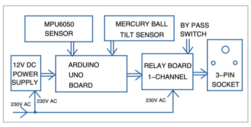
As shown in Fig. 2, the circuit built around Arduino Uno Board1 includes single-changeover relay module MOD1, MPU6050 module MOD2, mercury tilt switch module MOD3, 12V power supply, and a few other components. The block diagram is shown in Fig. 3.
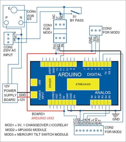
The output is connected to a single-channel relay board, which is connected to a 3-pin electrical socket for connecting to the electric iron. A bypass switch is used to bypass the relay board whenever smart action is not required. A 12V supply is used to power the Arduino board.
Accelerometer and gyroscope module
The MPU6050 accelerometer cum gyroscope module has eight pins, but only five pins are used to interface with Arduino Uno board in this project. The module is a micro electro-mechanical system (MEMS) with 3-axis accelerometer and 3-axis gyroscope inside it. This facilitates calculation of acceleration, velocity, orientation, displacement, and many other motion related parameters of a system or an object. The MPU6050 module is shown in Fig. 4.
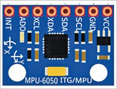
MPU6050 works on +3V to +5V power supply. In this circuit it is connected to +5V pin of Arduino Uno. Its serial clock (SCL) and serial data (SDA) pins are used for I2C communication between the module and Arduino Uno for providing clock pulse and for transferring data, respectively. The interrupt (INT) pin of Arduino is an output pin used to indicate that new data is available to be read from MPU6050.
MPU6050 module is placed inside or outside the iron box at a suitable position. Five wires are used to connect the module to Arduino Uno. Whenever the iron box moves during ironing, the positional data changes according to the movement of the iron box in different directions. The changes are analysed in the Arduino Uno board and, according to the program, the output relay energises and switches on the electric iron.
In this project, the iron’s position is tracked in x, y, and z directions. When the change in position or direction is detected, the relay gets switched on. The data from MPU6050 is read by Arduino Uno after a delay of one second. If the position or direction of the iron box is not likely to change during one second while ironing, a delay of two seconds can be given instead. The delay can be changed by changing the value of ‘i’ in the program.
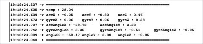
The output sample values (x, y, z) of MPU6050, as obtained in serial monitor, are shown in Fig. 5.
The mercury tilt switch module, shown in Fig. 6, can sense when it is tilted at an angle. It works because the mercury ball flows into the gap between two electrodes and closes the circuit when the module is tilted at an angle. The switch has pins for Gnd, Vcc, and Output. Its operating voltage is 5V.
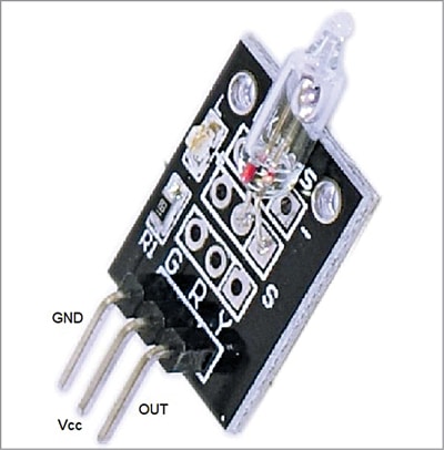
The tilt switch should be placed in the iron box in such a way that it switches off when iron is placed in vertical position. The three pins of the module should be extended to the circuit.
Single-pole, double-throw (SPDT) high-level trigger AC relay board, shown in Fig. 7, can be controlled directly via a microcontroller and switch up to 10A at 250V AC. The inputs of the relay module are isolated from 230V mains to protect the delicate control circuitry. The relay output pins are connected to 3-pin 250V, 6A electrical socket.
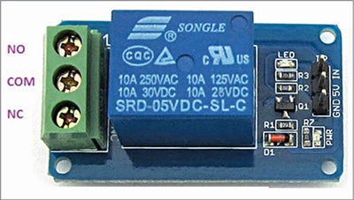
The phase of the 3-pin electrical socket is connected to normally open (NO) pin of the relay output pin. The neutral from the mains is connected to common (COM) pin of the relay module. An additional 6A SPST electrical switch (S1), connected across NO and normally closed (NC) terminals, acts as a bypass switch when smart switching action is not needed.
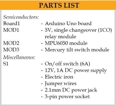 The Table shows pin connections between Arduino Uno board and various modules in the project. Arduino Uno is a microcontroller board based on 8-bit ATmega328P microcontroller, which is very simple to use and interface. Use a 12V, 1A SMPS power supply to power up the Arduino Uno board.
The software
The circuit operation is performed through the software program loaded into the internal memory of Arduino Uno. The program/sketch (ironbox.ino) is written in Arduino programming language. ATmega328P on Arduino Uno comes with a pre-programmed boot loader that allows users to upload a new code to it without using a peripheral hardware programmer.
Arduino IDE is used to compile and upload the program. The sketch is the heart of the system and carries out all major functions. The program is easy and simple to understand. Comments are given at the end of each command line. Fig. 8 shows the flow chart of the program.

When input and output pins of Arduino board are initialised, the following functions and libraries are used.
Serial.begin(). Establishes serial communication between Arduino Uno board and another device via a USB cable. It permits the two devices to communicate using a serial protocol. Here serial communication is used only to read the data from the MPU6050 via Arduino Uno onto the screen. The displayed data allows us to know the changes in the values during movement of the iron box. Sample values are shown in Fig. 5.
#include <Wire.h>. The Wire library allows communication through I2C devices, also called ‘2 wire’ or ‘TWI’ (two-wire interface). The SDA (data line) and SCL (clock line) are used for communicating with MPU6050 module.
#include <MPU6050_tockn.h>. It is the Arduino library for easy communication with the MPU6050 module. It can be downloaded from the link
mpu6050.update(). We must execute mpu6050.update() to fetch all the data from MPU6050.
 There are some important variables in the code. The ‘value_1’ variable sums up the angle values in the three directions at a time and passes the absolute value (negative sign is not considered). Similarly, ‘value_2’ variable sums up the angle values in the three directions at another point of time and passes the absolute value.
The ‘diff’ variable contains the difference of value_1 and value_2. When iron box is stationary, the diff value will be zero or close to zero. Based on the value in the diff variable, the movement of the iron box is detected. The ‘i’ value is used to provide some delay to switch off the relay after no movement of the iron box is detected.
Construction and testing
Fix a 6A, 250V electrical socket on top of a suitable plastic box. Enclose the whole circuit including Arduino Uno, 12V SMPS power supply, and the relay module inside the plastic box. The MPU6050 module and mercury tilt switch module should be placed inside the iron box at appropriate orientations to sense the vertical and horizontal positions of the iron box.
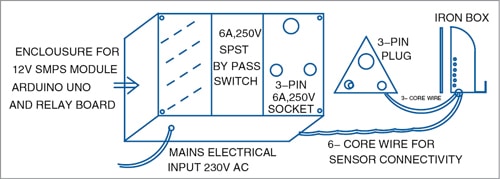
Use a 6-core soft cable to connect (common ground and common 5V, SDA, SCL, INT pins of MPU6050 module, signal out pin of tilt switch module) to the Arduino Uno module, which is enclosed in the plastic box. The relay remains switched on as long as the iron box is in motion, but it switches off when the iron box is placed in vertical position.
Use bypass switch S1 to disconnect the circuit when smart switch action is not needed. Fig. 9 shows the proposed construction details of the project.
Precautions
The Arduino Uno board is highly sensitive. Handle it carefully. Check the DC power supply jack input polarity (2.1mm centre-positive plug into the board’s power jack). Take care while placing the 12V SMPS module and the Arduino Uno board into the plastic switch box. Use of a 1000W iron box is recommended.
Choose an appropriate place inside or outside the iron box to place the sensors. The position of the tilt switch is very important. Place the tilt switch in such a way that it can detect vertical and horizontal positions of the iron box easily.
Download source code
K. Murali Krishna works as junior engineer at BSNL, Rajahmundry, Andhra Pradesh. He is an electronics enthusiast, circuit designer, and technical writer
excellent project
Thank you for your comment.