


 Small cooling fans are used in some equipment for cooling semiconductor devices. The circuit given here is of a simple automatic speed controller for a 12V, 0.6W (or 1.2W) cooling fan that increases the fan’s speed when temperature rises, and vice versa.
Circuit and working
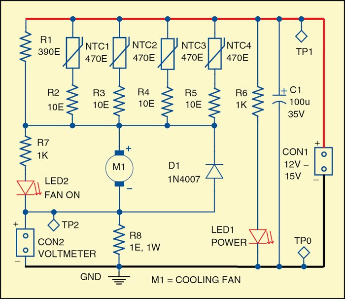
Fig. 1 shows circuit diagram of the speed controller for a small cooling fan. Resistor R1 limits the initial current for the motor and lowers the speed of rotation, if needed. The temperature control is done with one or more NTC (negative temperature coefficient) thermistors connected in series with the electrical motor. The number of thermistors depends on their power dissipation.
 Usually you cannot find low-cost NTCs with enough power dissipation. Therefore four of them in parallel are used here. This way power dissipation and self-heating of the NTCs are reduced. It is better to use NTCs with tolerance of ±2%. The NTCLE100E3 are available with nominal values of 3.3-ohm to 470-kilo-ohm and have maximum power dissipation of 0.5W at +55°C.

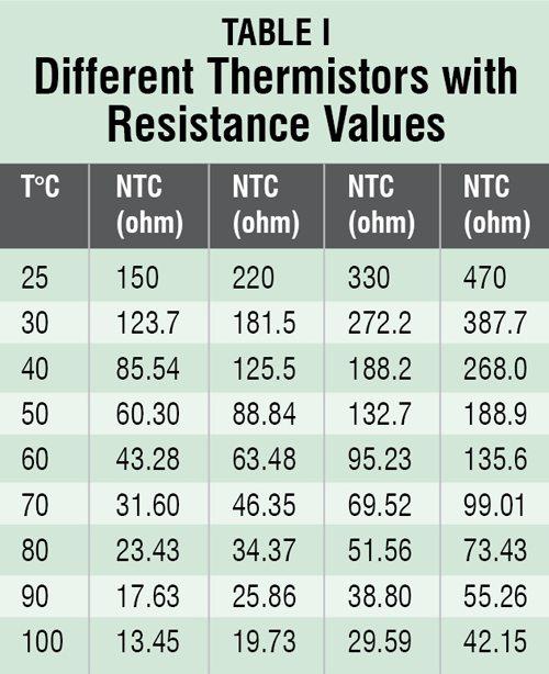
Table I shows easily-available NTC thermistors that can be used in the circuit. The resistors R2 through R5 are equalisation and limiting resistors. These resistors are usually between 3% and 15% of the resistance of the thermistors at +25°C.
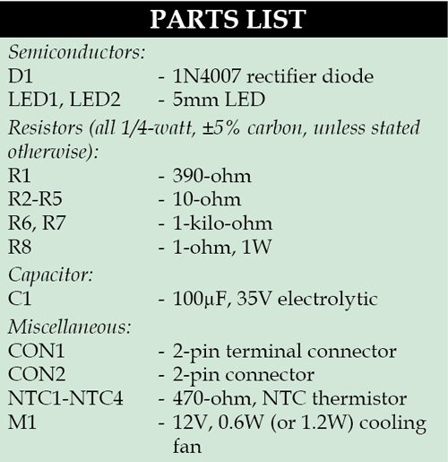 LED1 is used as power on/off indicator for the circuit. LED2 indicates the speed of rotation of the fan. If speed of the motor is high, LED2 glows brightly, and vice versa. Diode D1 is used to prevent back EMF when power supply is removed.
Connector CON1 is used for the power supply. It is better to have power supply 10 to 25% higher than the nominal working voltage of the fan to compensate for the voltage drop across the resistors and the thermistors.
Voltage drop across resistor R8 is proportional to the current in the motor. Connector CON2 is used to connect a digital voltmeter to measure the voltage drop.
Construction and testing
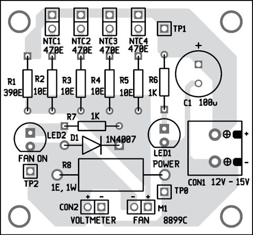
An actual-size, single-side PCB for the circuit is shown in Fig. 2 and its component layout in Fig. 3. After assembling the circuit on a PCB, enclose it in a suitable plastic box.
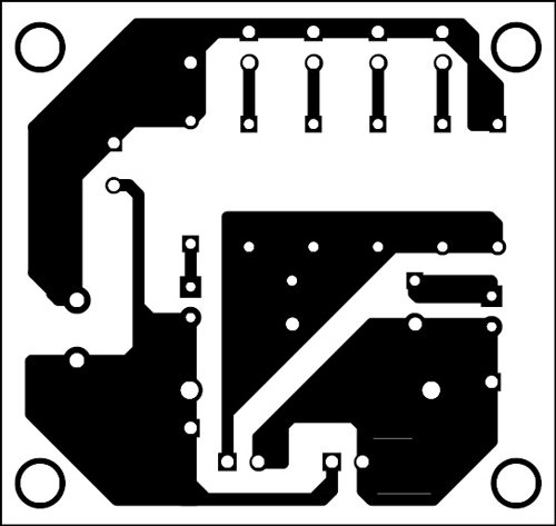
Download PCB and component layout PDFs: click here
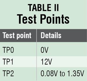
Fix all the four NTC thermistors (NTC1 through NTC4) at appropriate locations, within the equipment whose heat is to be dissipated, for temperature sensing. On front panel of the speed controller fix switch S1 for power on/off, LED1 for power on/off indication and LED2 for fan-speed indication. Before using the circuit, verify that voltages at various points in the circuit are as per Table II.
EFY note. All the four thermistors should be of same type.
The author was a researcher and assistant professor in Technical University of Sofia (Bulgaria) and expert-lecturer in OFPPT (Casablanca), Kingdom of Morocco. Now he is working as an electronics engineer in the private sector Bulgaria
