


Here is a simple, low-cost, energy-saving and device-saving circuit for an electronics lab, service centre, electronics workshop, or wherever a CRO is in use. A vibration sensor attached to a smart CRO probe senses motion when you pick up the probe and turns on the CRO. It turns the CRO off when the probe is idle for a specified amount of time.
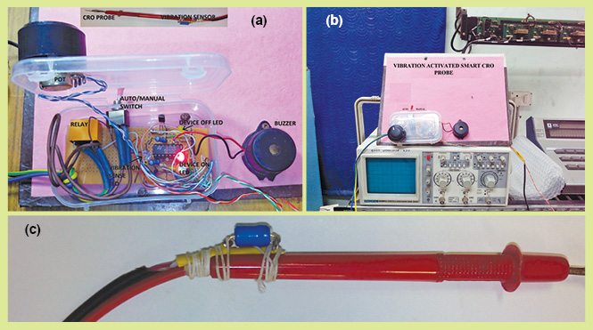
Generally, in a repair station, a CRO is used for a very short time. But in most cases, the user fails to switch off the CRO immediately after use. The service engineer mostly concentrates on faults rather than noticing whether the CRO is on or off. This results in wastage of power, reduction in CRO lifetime and leads to phosphorus burn in the cathode ray tube (CRT) due to electrons hitting the screen on the same spot for a very long time, which again leads to reduction of CRT lifetime. Fig. 1 shows the author’s prototype.
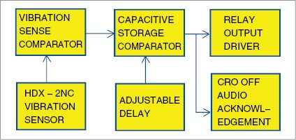
The block diagram of the vibration activated smart CRO probe is shown in Fig. 2. A vibration sensor fixed on the CRO probe senses the vibrations picked up by the probe. This vibration signal is sensed, stored in a capacitor, compared with a reference voltage and fed to the relay driver to switch on the CRO. An additional circuitry is provided to switch off the CRO and give an audio acknowledgement in the form of a beeping sound.

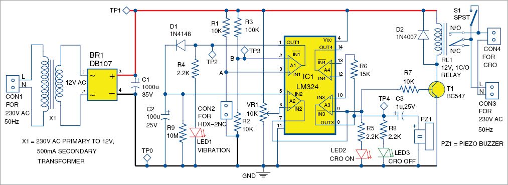
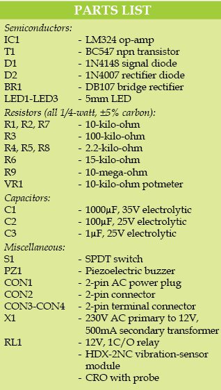
The circuit diagram of the vibration activated smart CRO probe is shown in Fig. 3. It is built around bridge rectifier DB107 (BR1), vibration sensor HDX-2NC connected across connector CON2, quad comparator LM324 (IC1), 1N4148 and 1N4007 diodes (D1 and D2), relay driver transistor BC547 (T1), 12V single-changeover relay (RL1) and a few other components.
Smart CRO probe circuit
As shown in Fig. 3, the circuit is built around IC LM324, which is a low-cost, quad operational amplifier (with four op-amps). Op-amps in this circuit are configured in comparator and inverted-buffer modes.
Here, HDX-2NC, a normally-closed vibration sensor is used. A vibration sensor is a small two-terminal component connected across connector CON2 in series with resistor R1. Point A in the circuit is connected to pin 3 of IC1, which is its non-inverting terminal. Under normal conditions, point A is connected to ground via sensor HDX-2NC. During vibration, its contact opens for a very small amount of time.
 Op-amp A1 acts as an input comparator. Resistors R2 and R3 act as potential dividers and produce around 1.2V at point B in the circuit. When there is vibration, 12V is produced at the non-inverting terminal of op-amp A1, which is greater than 1.2V at its inverting terminal. As a result, around 12V is produced at the output of A1. This is indicated by the glowing of vibration-sense indicator LED1.
The 12V produced at output of A1 charges capacitor C2 via diode D1. D1 allows the flow of current in only one direction, that is, from op-amp A1 to capacitor C2. Whenever there is a vibration, C2 charges to the maximum voltage and slowly discharges through resistor R9.
Maximum discharge time of C2 is around 30 minutes. Potmeter VR1 is used to set delay. Op-amp A2 is configured as a comparator, which compares the capacitor voltage against the set potmeter voltage. When C2 discharges, voltage decreases at the non-inverting terminal of A2. When voltage at C2 (pin 5 of A2) decreases beyond the set voltage (at pin 6 of A2), output of A2 at its pin 7 goes low. Output of A2 is connected to relay driver transistor T1.
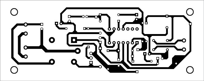
Download PCB and component layout PDFs: click here
When A2 output is high, relay RL1 energises and the CRO gets AC mains power supply via relay contacts to operate it. At the same time, the CRO-on indicator LED2 glows.
On time of the CRO can be set as per requirement using VR1. With a small voltage set via VR1 at inverting terminal pin 6 of A2, greater will be the delay. Similarly, with more voltage set, smaller will be the delay.
 An extra op-amp (A3) is used to provide acknowledgment to the user that the CRO has switched off after some idle time. For this, A3 is used in inverting-buffer mode. When output of A2 is high, output of A3 will be low, and vice versa.
When the CRO is off, output of A3 will be high. Due to this, the buzzer gets activated and produces a beep sound whose loudness gradually decreases within a short time. This happens because C3 initially acts as a short circuit and charges to +12V and blocks further current passing through the buzzer. Increasing C3 value makes the buzzer beep longer. This acknowledgement is like a communication between the user and the circuit. LED3 also flashes when the beeping sound is produced.
Auto and manual modes are provided by mode switch S1. When S1 is open, the circuit is in auto mode. With S1 closed, the circuit is in manual mode and bypasses the relay.
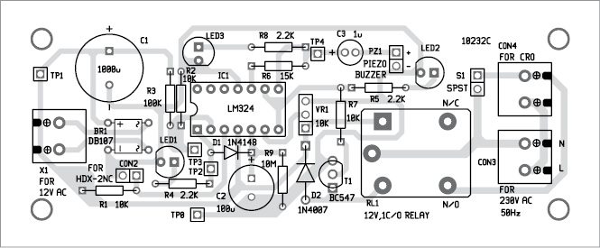
Construction and testing
A single side PCB for the vibration activated smart CRO probe is shown in Fig. 4 and its component layout in Fig. 5. After assembling the circuit on the PCB, enclose it in a suitable box. Connect 230V AC input across CON1 and CON3. Connect the CRO across CON4.
Fix the vibration sensor on top of the CRO probe as shown in Fig. 1(c). Use a highly-flexible and lightweight wire (like an earphone wire) to connect the sensor. Connect AC mains supply’s live wire L and neutral N across CON3.
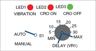
Potmeter VR1 is calibrated in terms of time. 10.45V is the maximum C2 charging voltage when sensor is subjected to vibration. During calibration mark the minimum (one minute) and maximum (25 minutes) delays. Proposed front-panel dial is shown in Fig. 6.
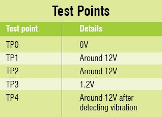
Provide proper insulation between AC and DC voltages. Ensure all test points have voltages as per the table before using the circuit. Main DC voltage at TP1 is unregulated.
I am doing my project on this so Please let me know that what is to be connected at con 3 & con 4.
CON3 is for connecting 230C AC mains and CON4 for connecting CRO as already indicated there in the PCB.
Is it good for digital oscilloscopes
Thank you for your feedback.
what transformer and relay did you use?
A step down transformer with 230V AC primary to 12V, 500mA secondary and a 12V, single changeover sugar cube relay are used