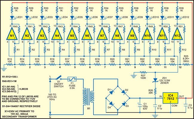
 You should not be surprised if someone tells you that the mains voltage fluctuation could be anywhere from 160 volts to 270 volts. Although majority of our electrical and electronics appliances have some kind of voltage stabilization internally built-in, more than 90 per cent of the faults in these appliances occur due to these power fluctuations. This simple AC mains voltage indicator circuit gives visual indication of AC mains voltage from 160 volts to 270 volts in steps of 10 volts.
There are twelve LEDs numbered LED1 to LED12 to indicate the voltage level. For input AC mains voltage of less than 160 volts, all the LEDs remain off. LED1 glows when the voltage reaches 160 volts, LED2 glows when the voltage reaches 170 volts and so on. The number of LEDs that glow keeps increasing with every additional 10 volts. When the input voltage reaches 270 volts, all the LEDs glow.
AC Mains Voltage Indicator
The circuit basically comprises three LM339 comparators (IC1, IC2 and IC3) and a 12V regulator (IC4). It is powered by regulated 12V DC. For power supply, mains 230V AC is stepped down to 15V AC by step-down transformer X1, rectified by a bridge rectifier comprising diodes D1 through D4, filtered by capacitor C4 and regulated by IC4. The input voltage of the regulator is also fed to the inverting inputs of gates N1 through N12 for controlling the level of the AC.

The LED-based display circuit is built around quad op-amp comparators IC1 through IC3. The inverting input of all the comparators is fed with the unregulated DC voltage, which is proportional to mains input, whereas the non-inverting inputs are derived from regulated output of IC4 through a series network of precision resistors to serve as reference DC voltages.
Resistors R13 to R25 are chosen such that the reference voltage at points 1 to 12 is 0.93V, 1.87V, 2.80V, 3.73V, 4.67V, 5.60V, 6.53V, 7.46V, 8.40V, 9.33V, 10.27V and 11.20V, respectively. When the input voltage varies from 160V AC to 270V AC, the DC voltage at the anode of ZD1 also varies accordingly. With input voltage varying from 160V to 270V, the output across filter capacitors C1 and C2 varies from 14.3V to 24.1V approximately. Zener ZD1 is used to drop fixed 12V and apply proportional voltages to all comparator stages (inverting pins). Whenever the voltage at the non-inverting input of the comparators goes high, the LED connected at the output glows.
Construction & testing
Assemble the circuit on a general purpose PCB such that all the LEDs make a bar graph. In the bar graph, mark LED1 for minimum level of 160V, then LED2 for 170V and so on. Finally, mark LED12 for maximum level of 270V.
Now your test gadget is ready to use. For measuring the AC voltage, simply plug the gadget into the mains AC measuring point, press switch S1 and observe the bar graph built around LEDs. Let’s assume that LED1 through LED6 glow. The measured voltage in this case is 220V. Similarly, if all the LEDs glow, it means that the voltage is more than 270V.
The article was first published in May 2006 and has recently been updated.


