


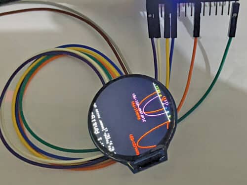
This Wi-Fi analysing smart watch is another version of the world’s first programmable smart  watch with fitness tracking project that was published in February issue. We want to customise it in such a way that it can help us analyse Wi-Fi networks and their data and signal strength. The author’s prototype of such a smart watch is shown in Fig. 1.
Wi-Fi signal and the network’s analysis is needed by the engineers while setting up Wi-Fi routers. It also helps us connect to the strongest Wi-Fi network signal available at a spot, besides being used as a tool by many cyber hackers. No smart watch provides the Wi-Fi analysis feature at present.
POC Video in English:

POC Video in Hindi:
| Bill of Material | ||
| Components | Quantity | Description |
| ESP12 F (MOD3) | 1 | SMD Wi-Fi SoC chip |
| MCP73812T (MOD4) | 1 | Battery charging IC |
| Round LCD (MOD1) | 1 | GC9A01 round LCD display |
| LED | 1 | SMD LED |
| Resistor 470Ω R2, 2kΩ R3, 100Ω R1 | 1 | SMD |
| Capacitor 4.7µF (C1, C2) | 2 | SMD ceramic |
| 2-pin jumper (JP1) | 1 | Jumper pin |
| Micro USB (MOD2) | 1 | SMD micro USB female |
| Switch (S1) | 1 | SMD slide switch |
| 3.3V battery | 1 | Microsize battery |
| 3D printed case | 1 | Body for watch |
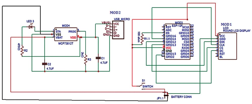
Circuit diagram of the Wi-Fi analysing smart watch is shown in Fig. 2. It is built around LCD (MOD1), USB micro cable (MOD2), ESP12F (MOD3), and MCP73812T (MOD4). Connect the components as per circuit diagram, which has two parts—first, voltage regulation plus 3.3V cell charging part and, second, the actual smart watch circuit that is connected to the battery through jumper pin JP1.
Software

