


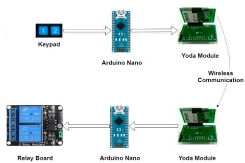
This Wireless Remote Control project is based on Yoda with an adapter and Arduino Nano. Electrical appliances (like fan and lights) can be controlled wirelessly using an RF remote.
This Project describes an Arduino based wireless Control appliances from Yoda adapter Remote. This project has a pair of Yoda adapter with an Arduino Nano board. Users can configure YODA modules as receiver and transmitter to control Relay On/Off switching from Zigbee Remote.
The Block diagram of the projects is shown in fig 1.

| Table а: List of components | |
| Name | Quantity |
| Arduino Nano boards | 2 |
| Yoda Zigbee Coordinator Module | 1 |
| Yoda Zigbee Endnode Module | 1 |
| Yoda Zigbee Adapter boards | 2 |
| 10K Ω resistor | 2 |
| Push Button | 2 |
| 2 Channel 5V Relay Board | 1 |
| 5V 1.5A DC Power Adapter | 1 |
| DC jack for Power Adapter | 1 |
| Breadboards | 2 |
| Some breadboard wires | |
(For Yoda Adapter Manual and Yoda Command Set please visit this webpage)
Circuit and working
Configure Yoda Zigbee Module
- Required software and installation file: Docklight, MCP2200/MCP2221 Windows Driver & Installer
- Each YODA should be configured with common Channel and PAN ID values to interact/communicate between YODAs.
Procedure to configure YODA
- Open Yoda Configuration Command Docklight file.
- Interface Yoda Zigbee modules with Yoda Zigbee Adapter board and connect to PC/Laptop with the help of micro USB cable.
- Configure channel and PAN-ID with the help of Write command in both Zigbee modules.
- Execute Read command for confirming the configuration.
- Restart/reset both YODA modules.
- Check communication between both modules by sending Data Command between each other.
- If communication is happening between both modules, then the user is ready for interfacing these devices with a custom project.
Constructing the Transmitter Circuit
Use Yoda Zigbee Coordinator module and make connections on one breadboard according to the Transmitter schematic given in Figure 2.
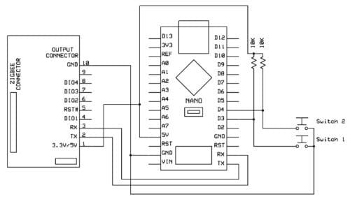
Figure 3 can be used as a reference for making transmitter connections on the breadboard.
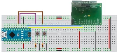
Connect one end of micro USB cable to Aurdino nano board and other end to PC/Desktop to power On Transmitter circuit.
Constructing the Receiver Circuit
Use YODA (End-node) module and make connections on one breadboard according to the receiver schematic given in Figure 4.
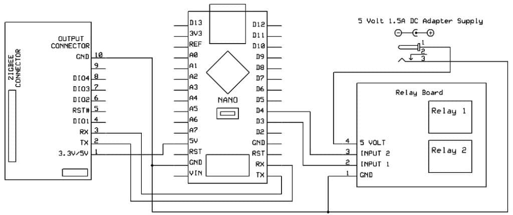
As Arduino Nano board can’t provide sufficient current to Relay Board, has to use an external DC 5V power adapter for powering On Relay Board.
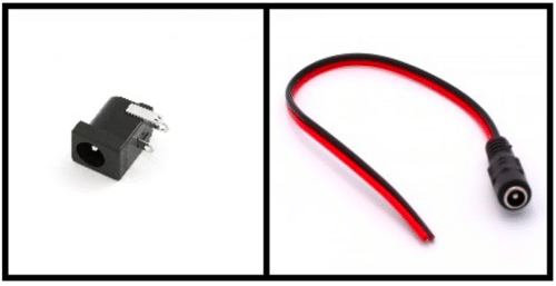
Connection to make 5V DC power adapter to power On relay circuit: use a DC Jack/Socket as shown in figure 5(a) or use DC socket with the wire as shown in figure 5(b), For using a DC socket which is shown in figure 5(a), solder two wires as shown in figure 6 to use it in the breadboard.
A black color male to male dupont jumper wire can be solder on a negative terminal for giving a connection to the breadboard and a Red color male to female dupont wire can be solder to a positive terminal for giving a connection to the relay Board.
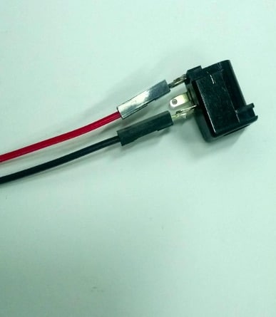
Figure 7 can be used as a reference for making receiver connections on the breadboard.
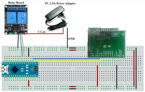
Connect one end of micro USB cable to Aurdino nano board and another end to PC/Desktop to power on the receiver circuit. Connect 5V 1.5A DC adapter to relay circuit to Power On.
Software
- Arduino Nano: Software is written in Arduino programming language which provides the simple capability of serial communication via UART, SPI & I2C.
- Required software and installation file: Arduino IDE.
Procedure for Receiver Arduino Nano Code:
- Open a new Arduino Nano sketch.
- Copy the given receiver code in it. Save as “Relay_Rx”.
- Remove Zigbee UART wires (wires which are connected on Rx and Tx pins of Nano) from
- Arduino Nano, as Arduino IDE uses the same serial port for uploading code.
- Compile the code and upload it in Receiver circuit Arduino Nano.
- Connect back Zigbee UART wires on Arduino Nano.
/********************************
//
// Receiver Arduino Nano Code
//
********************************/
// For Relay Pin Assignment
const int Relay1Pin = 3;
const int Relay2Pin = 4;
bool Relay1_State = false;
bool Relay2_State = false;
char incomingByte ; //Variable to store the incoming byte
void setup() {
Serial.begin(9600);
pinMode(Relay1Pin, OUTPUT);
pinMode(Relay2Pin, OUTPUT);
digitalWrite(Relay1Pin, LOW);
digitalWrite(Relay2Pin, LOW);
delay(5000); //delay for Zigbee modules to start/join network
}
void loop() {
if (Serial.available()) {
incomingByte = Serial.read(); //Read the incoming byte
switch (incomingByte)
{
case 1:
{
Relay1_State = !Relay1_State;
if (true == Relay1_State){
digitalWrite(Relay1Pin, HIGH); //Relay 1 Switch ON
}
else{
digitalWrite(Relay1Pin, LOW); //Relay 1 Switch OFF
}
break;
}
case 2:
{
Relay2_State = !Relay2_State;
if (true == Relay2_State){
digitalWrite(Relay2Pin, HIGH); //Relay 2 Switch ON
}
else{
digitalWrite(Relay2Pin, LOW); //Relay 2 Switch OFF
}
break;
}
default:
{
break;
}
}
}
}
Procedure for Transmitter Arduino Nano Code:
- Open a new Arduino Nano sketch.
- Copy given Transmitter code in it. Save as “Remote”.
- Remove Zigbee UART wires (wires which are connected on Rx and Tx pins of Nano) from Arduino Nano, as Arduino IDE uses the same serial port for uploading code.
- Compile the code and upload it in the Transmitter circuit Arduino Nano.
- Connect back Zigbee UART wires on Arduino Nano.
/***********************************
//
// Transmitter Arduino Nano Code
//
***********************************/
const int Switch1 = 3; //Switch at D3
const int Switch2 = 4; //Switch at D4
const int Debounce_Delay = 100;
void setup() {
Serial.begin(9600);
// initialize the pushbutton pin as an input:
pinMode(Switch1, INPUT);
pinMode(Switch2, INPUT);
delay(5000); //delay for Zigbee modules to start/join network
}
void loop() {
if(0 == digitalRead(Switch1)) // If Switch 1 pressed
{
delay(Debounce_Delay);
if(0 == digitalRead(Switch1))
{
//Send the message:
Serial.write(0x4D);
Serial.write(0x08);
Serial.write(0xFF);
Serial.write(0xFF);
Serial.write(0xFF);
Serial.write(0x07);
Serial.write(0x01); //Sending Switch Number
while(0 == digitalRead(Switch1)); //Waiting for release of switch
}
}
if(0 == digitalRead(Switch2)) // If Switch 2 pressed
{
delay(Debounce_Delay);
if(0 == digitalRead(Switch2))
{
//Send the message:
Serial.write(0x4D);
Serial.write(0x08);
Serial.write(0xFF);
Serial.write(0xFF);
Serial.write(0xFF);
Serial.write(0x07);
Serial.write(0x02); //Sending Switch Number
while(0 == digitalRead(Switch2)); //Waiting for release of switch
}
}
}
Testing setup
- Power On Transmitter setup first, as Zigbee coordinator is responsible for starting the Zigbee network.
- Power On receiver setup circuit and wait for 5 seconds since given 5 seconds delay in receiver function.
- Press push buttons in the Remote circuit for switching On and Off Relay. Relay On means Load is ON else OFF.
Rajesh Sood is the Chief Marketing Officer and Piyush Gupta is the Senior Software Engineer at Si2 Microsystems Pvt. Ltd
