


 This is an IoT based Automated table lamp that works in such a way that whenever a person sits on the chair it automatically turns on and when the person leaves the chair it automatically turns off. This IoT project also has bed-time alert feature to indicate it’s time to sleep when it turns off the lamp automatically and gives ‘Time to Sleep’ notification on your mobile phone. You can also manually control the lamp on/off from the Blynk app on your smartphone.

Circuit and working
At the heart of this IoT project are two NodeMCU ESP8266 boards, Board1 and Board2, and an IR sensor module. Board1 with IR sensor is used as transmitter to send the signals collected by the sensor, which is fixed on the chair, through a mobile network. Board2 with the lamp is used as receiver to collect the signals.
The IR sensor connected to Board1 checks whether a person is sitting on the chair or not. Whenever a person sits on the chair the state of IR sensor becomes high. The IR sensor always sends real-time data to the receiver. As soon as the state becomes high, the sensor data is processed by first NodeMCU that sends the data to smartphone and to the second NodeMCU in the receiver to turn on the lamp. When one gets up from the chair, the data from the transmitter is sent to the receiver to turn off the lamp.
The bed-time alert is set by the user in the smartphone through Blynk app. This set time is sent to Board2 to turn off the lamp. Both the NodeMCU boards are connected to the Wi-Fi network or a mobile phone’s hotspot.
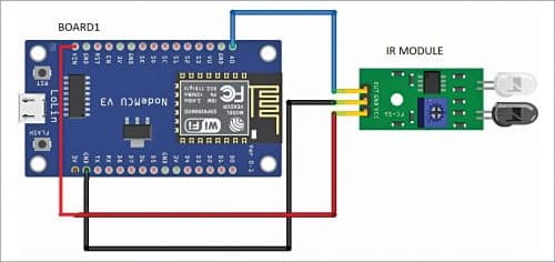
Connection diagram of transmitter with IR sensor is shown in Fig. 1 and the pin-to-pin connections are shown in Table 1. Connection diagram of receiver with lamp is shown in Fig. 2 and pin connections in Table 2.


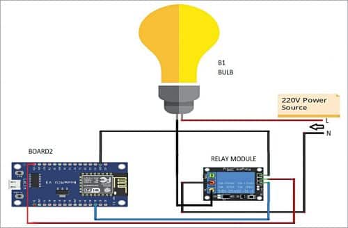
The AC lamp has line (L) and neutral (N) wires. Connect the neutral wire between the normally-closed (NC) pin and the common pin of the relay module.
Software
Arduino IDE (integrated development environment) and Blynk app software are used in this project.
Arduino IDE
The Arduino IDE is the program used to write Arduino code. It comes in the form of a downloadable file on the Arduino website. The Arduino board is the physical board that stores and executes the program code uploaded to it. The software package and the board together are referred to as Arduino.
Blynk
Blynk IoT platform offers a full suite of software that allows to prototype, deploy, and remotely manage connected electronic devices at any scale, from small IoT projects to millions of commercial connected products.
Hardware and software setup
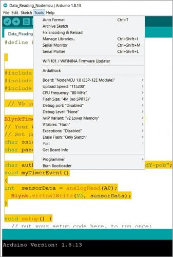
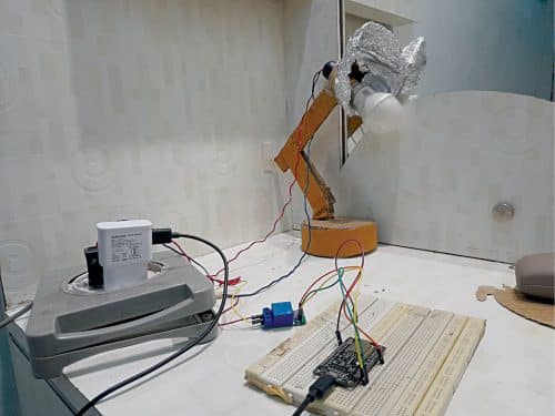
Connect NodeMCU to your PC. Open the Arduino code transmitter_IR.ino from Arduino IDE and select the correct board and COM port from Arduino IDE. Select the board as NodeMCU 1.0 (ESP-12E module) as shown in Fig. 3. The author’s IR sensor transmitter fixed on the chair is shown in Fig. 4 and author’s receiver circuit wired on breadboard is shown in Fig. 5.
Before proceeding further, make sure you have the following libraries installed in your Arduino IDE:
- Blynk library
- Blynk simple library
- ESP8266 Wi-Fi library

Before uploading the code transmitter_IR.ino to Board1, you need to include your own SSID, password, authorisataion token in the code and compile it. Similarly, include these details in the receiver code reciever_lamp.ino in Board2. The authorisation token is generated from Blynk app, which is explained below.
Blynk app configuration
1. Download the Blynk app in your smartphone from Play Store or from App Store.
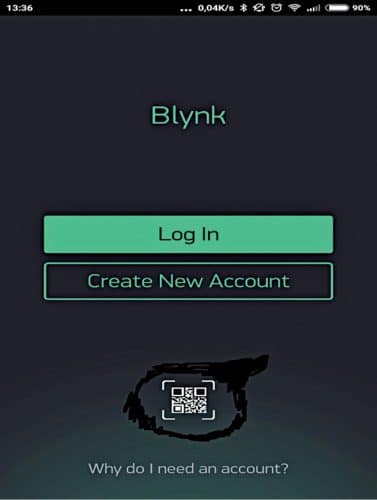
2. Log in if you have Blynk account, or just sign up to create a new account as shown in Fig. 6.
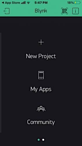
3. Select the New Project option as shown in Fig. 7.
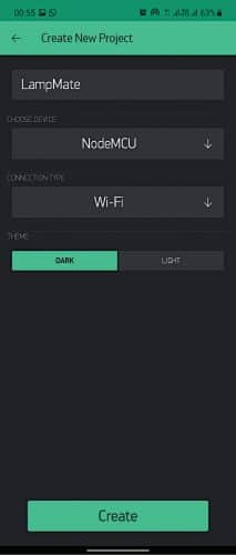
4. You will see a ‘Create New Project’ screen as shown in Fig. 8. Give a project name, say, LampMate, and choose your device as NodeMCU. You will see another option asking for Connectivity. Set it as Wi-Fi and click on Create button.
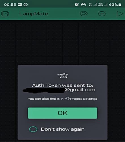
5. Now you will see a pop-up window as shown in Fig. 9. Authentication token will be sent to your registered email. The generated token is used in the Arduino codes for NodeMCU connection with the Internet.
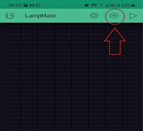
6. Click on the + (plus) icon on top right corner of the screen as shown in Fig. 10.
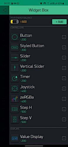
7. You will see a widget box as shown in Fig. 11. Add all the necessary widgets such as Button, Gauge, Notification, and Eventor.
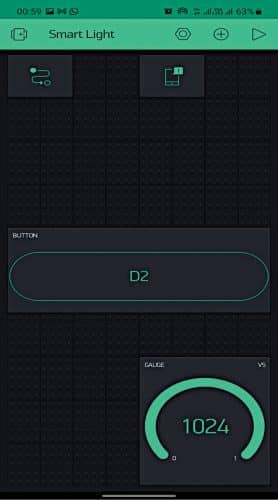
8. Arrange the widgets in the desired manner as shown in Fig. 12.
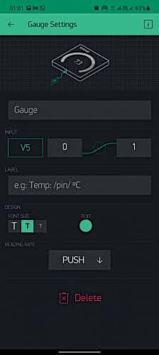
9. To read the IR sensor values, you need Gauge widget. For that click on Gauge, select the digital pin as V5 from the INPUT option as shown in Fig. 13.
10. After all the above-mentioned steps, click Play button on top right side of the control panel. Next, check the maximum and minimum readings of the sensor on the Gauge widget by placing your hand in front of the IR sensor. In this case, the maximum value is set to 1024 and the minimum to 40.
11. Click on Eventor button to add new event by clicking +Add New Event as shown in Fig. 14.
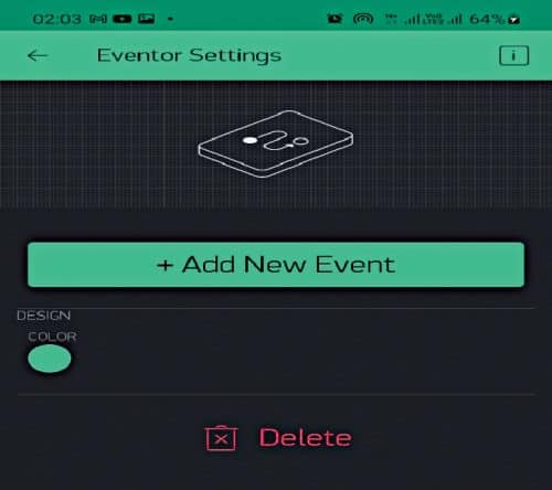
12. Follow the steps to setup the new events.
13. You will see an option to set Vpin value. Click on that and select V5 option and then click OK as shown in Fig. 15.
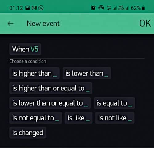
14. You will now see another screen to choose the higher and lower conditions for the sensor input data. Choose these values according to the readings generated by the IR sensor. You can select the lower value as 40 or just above that. Here, the lower value is 50 as shown in Fig. 16.

15. Now you will be prompted to take action. Select ‘Turn off D2’ command to turn the lamp on and click OK as shown in Fig. 17. It is because the relay module is connected to D2 pin of NodeMCU (Board2). See the relay module pin details in Fig.18.
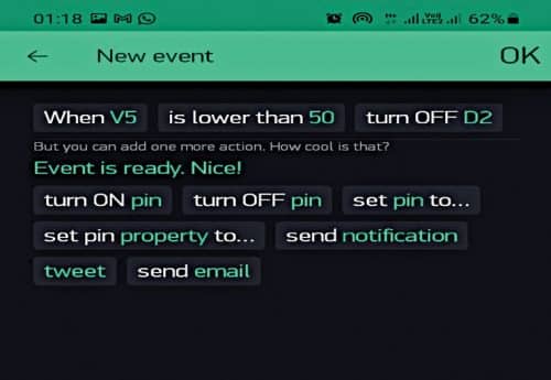
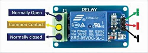
(Note. Relay model works like an on/off switch. As you can see from its pinout details, there are three pins: NC (normally-closed), NO (normally-open) and COM (common). The lamp is connected to NC, so whenever you connect it to the power supply, the lamp automatically turns on. So, for this reason when the turn-on command is sent, it actually turns off the lamp, and when the turn-off command is sent, the lamp turns on.)
16. Do the same way here as you did in the previous step, but here you have to command ‘Turn on D2’ as shown in Fig. 19. With this command the lamp will turn off. Note that you need to select this condition according to the readings from IR sensor. In this example, maximum reading is 1024. So, when V5 is equal to 1024, it will turn the lamp off.
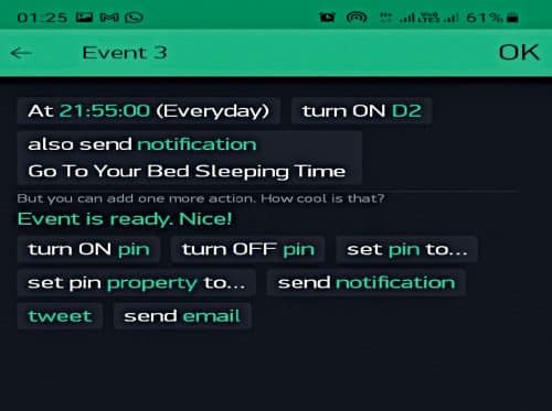
17. To set the bed-time alert, click on the Time option from +Add New Event. Then select the day of the week, the time (either start time to turn-on the lamp or time to turn-off the lamp for bed time), and your time zone. Then click on ‘Set the time’ as shown in Fig. 20.

18. You will be prompted to take action. Choose ‘Turn on D2’ and select notification option and set your text like “Go to bed, it’s time to sleep,” and then click OK.
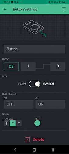
19. Click on Button to configure its settings. Select OUPUT as D2, replace ‘1’ with ‘0’ and ‘0’ with ‘1’ and change the mode from Push to Switch as shown in Fig. 21.
Next, connect Board1 and Board2 to the power supply. Click on Play icon; Blynk app will automatically connect to the NodeMCU boards. Turn on the lamp either by touching the D2 button from the Blynk app or by sitting on the chair. That’s it! You are good to go!
Download Source Code
Rohan Barnwal is an electronics hobbyist

Can u provide the code. It would be a great help
Hi Kunal, you can download the source code from the end of the page and I have sent you the code via email also.
Can u provide the code
We have sent the Source code via email.