


 Presented here is an Internet of Things (IoT)-based controller for a smart home. This IoT project can be used to control any four home electrical appliances such as lights, fans, air-conditioners and water pumps from the smartphone.
In this project, we used two light bulbs, one DHT-11 sensor to monitor room temperature and humidity, one soil moisture sensor along with garden motor pump, and one ultrasonic sensor (HC-SR04) for water-level indication in overhead water tank. Their status, including light on/off, room temperature, soil moisture level and water level, could be monitored on the smartphone graphically.
Circuit and working
The circuit diagram of the IoT-based smart home device controller is shown in Fig. 1. It is built around NodeMCU (ESP1), two light bulbs (Load3 and Load2), four 12V single-changeover relays (RL1 through RL4), 5V regulator 7805 (IC1), temperature and humidity sensor (DHT11), 5V DC soil moisture sensor, ultrasonic sensor (HC-SR04) and a few other components.

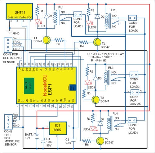
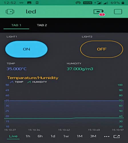
In this IoT project, Load3 (Light1) and Load2 (Light2) are controlled through RL3 and RL2, respectively. DHT11 sensor is used to monitor room temperature and humidity. In Blynk app, virtual levels V5 and V6 are used to display humidity and temperature, respectively. For that, we used Blynk.virtualWrite(V5, h) and Blynk.virtualWrite(V6, t) in the code.
Soil moisture sensor is used to detect garden soil moisture level. If soil is dry, the garden motor pump turns on automatically to pump out water for the plant.
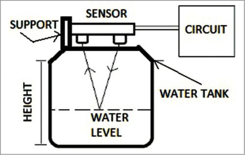
Ultrasonic sensor (HC-SR04) is used to detect water level in the overhead water tank (refer Fig. 11). Height of the tank used in the prototype is 20cm. If distance measured by the sensor is 0cm, the app will show the tank as full; and if distance is 20cm, it will show the tank as empty.
As shown in the circuit, pins D0 and D1 of NodeMCU are connected to pins Trig and Echo of HC-SR04, respectively. Water level is monitored through HC-SR04 sensor, and water motor pump can be controlled through RL1, which is connected to pin D6 of NodeMCU.
DHT11 sensor is connected to pin D2 of NodeMCU. Garden motor pump is controlled through RL4, which is connected to pin D3 of NodeMCU.
When power is switched on by connecting 12V battery, NodeMCU gets connected to Wi-Fi network. Open Blynk app on the mobile to start controlling the electrical appliances. But before that you need the required software in NodeMCU.
Arduino IDE is needed to write Arduino code and upload the programming logic onto NodeMCU board. Blynk app is required on the Android smartphone. Note that, authorisation code generated from Blynk app will be required in Arduino code. For that, create project in Blynk app.
Creating a project on Blynk IoT platform
Steps to create the project in Blynk are given below.
Install Blynk app on Android smartphone from Play Store. Register yourself on the app. You will get an authentication token on your registered email ID submitted during the registration process. Note it down as you will need it for Arduino code later.
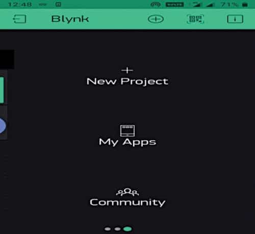
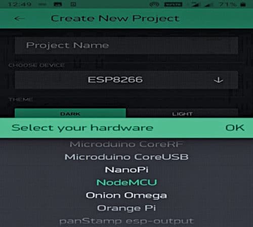
After registration, login to Blynk app and create your project by selecting New Project (Fig. 2). Name the project with a suitable title and select the module as NodeMCU (Fig. 3).
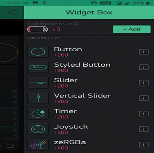
Now, open widget and select Buttons (Fig. 4). You will now see another screen where you can add label value to display temperature, humidity, super chart for graphical representation, etc.
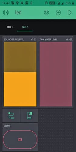
Add two control tabs: Tab1 and Tab2 (Fig. 5). Under Tab1, add Light1 and Light2 for controlling Load3 and Load2, respectively. Under Tab2, add two levels, V7 and V8, to display soil resistance and water level, respectively. You can also add eventor and notification to get notifications on a particular event.
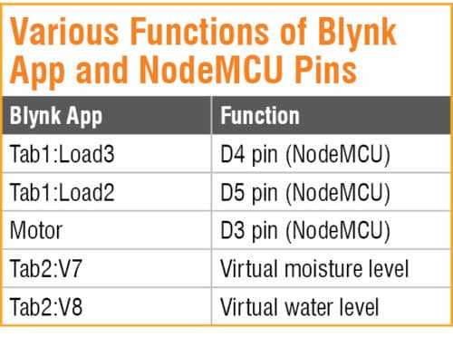
Now, link all controls in Blynk app and pins of NodeMCU, as given in Table above.
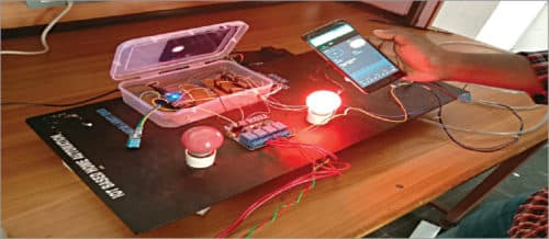
The author’s prototype is shown in Fig. 8.
Next, open smart_home.ino code from Arduino IDE. Configure NodeMCU with Wi-Fi credentials and paste the authorisation code generated from Blynk app. Compile the code and upload it onto NodeMCU board.
Construction and testing
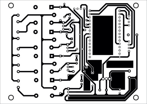
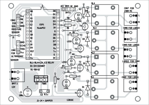
You can assemble the circuit on a veroboard or on the designed PCB given here. An actual-size PCB layout for the IoT-based device controller for smart home is shown in Fig. 9 and its components layout in Fig. 10.
Download PCB and component layout PDFs: click here
Download Source Folder
After assembling the circuit, enclose it in a suitable plastic box. Power on the circuit. Open the project from Blynk app to check whether all devices are connected to the Internet. If they are connected, red mark on the app will disappear.
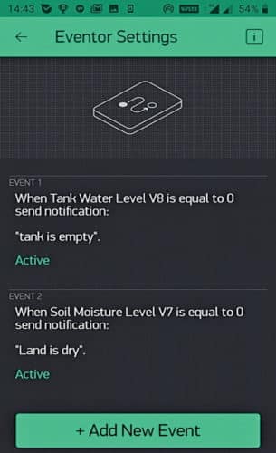
You can start controlling the devices by touching the corresponding buttons on the app. Garden motor pump is controlled through pin D3 of NodeMCU. You can turn it on/off through the app or manually. You can monitor water level in overhead water tank from the app, and if the tank is full, you can manually turn off the motor. In case you want to operate the motor automatically, add Event in Event Manager when tank is empty or full.
K. Muni Sekhar Reddy is lecturer in ECE department, government polytechnic, Rayachoty, Andhra Pradesh
Palla Siva Kumari is lecturer in EEE department, Government Polytechnic, Rayachoty, Andhra Pradesh

We are pleased to collaborate in the développement industriel for Energy management and photovoltaïque for self Energy production