


Infrared Audio Communication is a method of transmitting sound wirelessly using pulses of invisible light rather than radio waves. It works by modulating the intensity of an IR LED to match the fluctuations of an audio signal. At the other end, a phototransistor, or a IR light sensing diode captures the flickering light and converts it back into electrical current which is then amplified to drive a speaker.
This technology is useful in applications such as secure room-to-room communication, assistive listening systems in theatres and conference halls, wireless headphone systems, and environments where radio-frequency signals are restricted or may cause interference, such as hospitals and laboratories. Because infrared light does not pass through walls, it also offers an added layer of privacy compared to traditional RF-based systems.
This intermediate-level project is the basic prototype of Li-Fi based systems, and is cheaper to build on a breadboard as it does not use any microcontroller or uncommon ICs, and materials. With a few Analog Electronics concepts, anyone can make this project easily.

Circuit Description
This project includes two circuits, the one for audio transmission and the second for audio receiving.
The transmission circuit, Fig. 1, uses the audio input directly from a mobile phone or a laptop, then it is entered into the audio power amplifier through the stopping capacitor-resistor network, which also works as a passive high pass filter. LM386 is a kind of audio integrated power amplifier, which has the advantages of low power consumption, adjustable internal chain gain, and wide supply voltage gain. The input signal is very weak, thus it can be configured with a gain of 50-200 times, increase the transmission energy and enlarge the receiving distance using LM386 before IR LED. Then, the amplified signal is transmitted through an IR emitting channel.
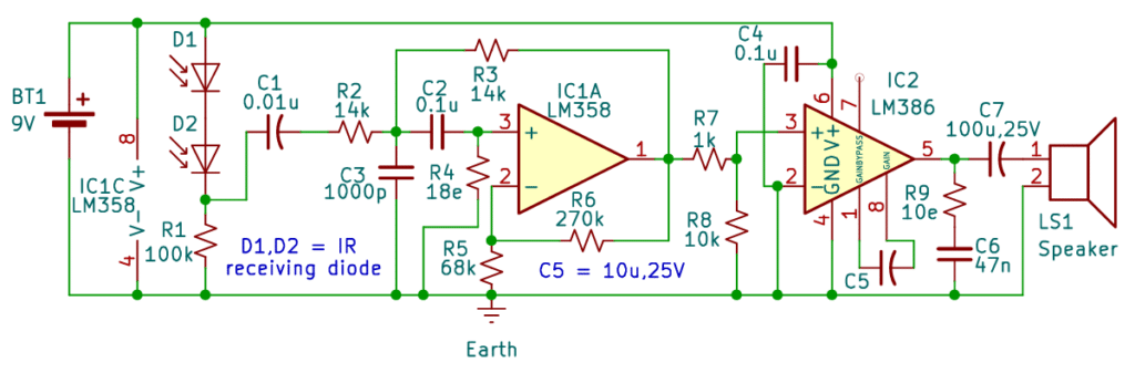
The receiver circuit, Fig. 2, uses the IR receiving channel, by which the optical signal is received, and then converted into the electrical signal using a band pass filter. LM358 is a dual op-amp, which has advantages of high gain, and internal frequency compensation. It can be used in a single power supply and has a wide input voltage range. Thus, LM358 can be used as a band pass filter in this circuit. It is configured with a range of frequency from 160Hz to 11000Hz using appropriate values of resistors and capacitors, filtering out other frequency signals and noise. This filtered signal is still weak and not sufficient to drive a speaker or headphone. Therefore, LM386 is needed to amplify the filtered signal and then drive the speaker to work normally.
The tested range for this circuit is approximately 4 metres. It can vary according to the environmental conditions, such as ambient light and sunlight.
| Parts List |
| Transmitter circuit: Semiconductors IC1 – LM386 audio power amplifier D1,D2 – IR emitting diode Resistors(All ¼-watt, 5% carbon film) R1,R2 – 2kΩ R3 – 100kΩ R4 – 10Ω R5 – 1kΩ R6 – 47Ω Capacitors C1 – 100nF ceramic disc C2 – 100nF ceramic disc C3 – 10µF, 25V electrolytic C4 – 47nF ceramic disc Miscellaneous J1 – Audio jack input BT1 – 9V PP3 battery with battery clip PCB (general-purpose or custom-made) or breadboard IC base (8-pin for LM358) Connecting/ jumper wires Receiver circuit: Semiconductors IC1 – LM358 operational amplifier IC2 – LM386 audio power amplifier D1,D2 – IR receiving diode Resistors(All ¼-watt, 5% carbon film) R1 – 100kΩ R2,R3 – 14kΩ(2 Nos.) R4 – 18Ω R5 – 68kΩ R6 – 270kΩ R7 – 1kΩ R8 – 10kΩ R9 – 10Ω Capacitors C1 – 0.01µF ceramic disc C2,C4 – 0.1µF ceramic disc(2 Nos.) C3 – 1000pF, ceramic disc C5 – 10µF, 25V electrolytic C6 – 47nF, ceramic disc C7 – 100µF, 25V electrolytic Miscellaneous LS1 – 8Ω speaker BT1 – 9V PP3 battery with battery clip PCB (general-purpose or custom-made) or breadboard IC bases (8-pin for LM358 and LM386) Connecting/ jumper wires |
Circuit Diagram
Learning points
- Learn to make wireless audio transmission systems using discrete components.
- Learn the concept of a bandpass filter and gain in an op amp.
- Learn the concept of IR transmitting and receiving diodes.
- Develop practical debugging skills and awareness of noise and grounding issues in analog circuits.