


 This project aims to display the information entered in a mobile phone on an LED dot-matrix type scrolling display. It is done by interfacing a Bluetooth HC-05 module to an LED dot-matrix display using an STM32 board.
The STM32 board, also known as Blue Pill development board, incorporates STM32F103C8T6 microcontroller from STMicroelectronics. It is a 32-bit ARM Cortex M3 controller with high clock frequency that is suitable for high-speed and power constraint applications.
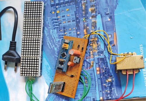
LED dot-matrix is a widely used display that is seen in digital clocks at railway stations, airports, etc to show arrival and departure time of trains and airplanes. Components required for the project are listed under Bill of Material table. Author’s prototype of the LED dot-matrix scrolling display using STM32 controller is shown in Fig. 1.

As shown in Fig. 2, the dot-matrix LED module incorporates an MAX7219 driver chip. The module has an 8×8 LED matrix, each LED of which is controlled precisely by the MAX7219 driver to generate the colour pattern or text you wish to see. Thus, you have control over all the 64 LEDs by connecting the module just through three wires to microcontrollers like Arduino, NodeMCU, ESP32, STM32, etc.
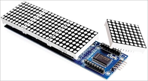
This module has four dot-matrix LEDs cascaded to form a single LED display to allot more area to the user on the display. Connecting two such modules is easy; just connect output pins of the previous display to input pins of the next display. This way any number of dot-matrix LED modules can be connected to an Arduino, NodeMCU, ESP32, or STM32.
The MAX7219 dot-matrix LED module has a serial input common-cathode driver that interfaces microcontrollers to LED matrices. All common microcontrollers can be connected to this module by using a 4-wire serial interface. Each output can be addressed without refreshing the entire display.
This module requires only three input/output lines for driving the display, making it ideal for microcontroller projects. Only one external register is used to set the segment current of each LED.
| Table 1: Bill of Material |
| • MAX7219 LED Dot Matrix Display (1088AS) |
| • STM32 (Blue Pill) Development Board |
| • HC-05 Bluetooth Module |
| • 5V Regulated Power Supply |
| • General-Purpose PCB/Bread board |
| • Jumper Wires |
HC-05 Bluetooth is used for applications like wireless headset, game controllers, wireless mouse, wireless keyboard, besides some other consumer applications and student projects. It has a range up to 100 metres, which depends on the transmitter and receiver used, the atmosphere, and geographic as well as urban conditions.
HC-05 uses IEEE 802.15.1 standardised protocol through which one can build wireless personal area network (PAN). It uses frequency-hopping spread spectrum radio technology to send data over air and serial communication to communicate with devices. It communicates with the microcontroller using serial port with a universal baud rate of 9600 bps.
HC-05 is a Bluetooth module designed for wireless communication. The module can be used in a master or slave configuration. Fig. 3 shows how it looks.
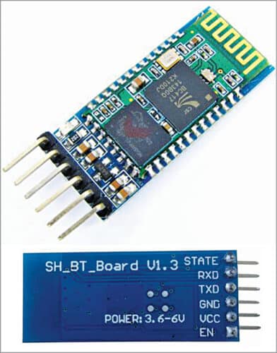
Fig. 4 shows the Blue Pill controller, which costs very less compared to an Arduino board. The hardware is open source. The microcontroller in it is the STM32F103C8T6 from STMicroelectronics.

The board also has an 8MHz crystal oscillator and a 32kHz crystal oscillator, which can be used to drive the internal real-time clock (RTC). Because of this, the microcontroller can operate in deep-sleep mode, making it ideal for battery operated applications.
The ARM Cortex M3 STM32F103C8 microcontroller is used in the Blue Pill board. The microcontroller nomenclature STM32F103C8T6 has a meaning behind it:
- STM stands for the manufacturer’s name STMicroelectronics
- 32 stands for 32-bit ARM architecture
- F103 indicates the architecture ARM Cortex M3
- C stands for 48-pin structure
- 8 stands for the 64kB Flash memory
- T indicates package type is LQFP
- 6 for operating temperature of -40°C to +85°C
Circuit and working
Circuit diagram of the LED dot-matrix scrolling display circuit can be divided into two parts—the regulated power supply and the control circuit.
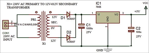
The regulated power supply is shown in Fig. 5. It has a full-wave rectifier built around 1N4007 rectifier diodes (D1, D2) and a 5V voltage regulator (IC1). Its centre-tapped transformer X1 reduces 230V AC mains to 12V-0-12V, 500mA. The capacitors C1 and C2 filter the ripples. The regulated 5V (Vcc) output from IC1 is used to power the circuit.
| Table 2: Specifications of the STM32 (Blue Pill) | |
| Name | Description |
| Architecture | 32-bit ARM Cortex M3 |
| Operating voltage | 2.7V to 3.6V |
| CPU frequency | 72MHz |
| Number of GPIO pins | 37 |
| Number of PWM pins | 12 |
| Analog input pins | 10 (12-bit) |
| USART peripherals | 3 |
| I2C peripherals | 2 |
| SPI peripherals | 2 |
| Can 2.0 peripheral | 1 |
| Timers | 3 (16-bit) (1 PWM) |
| Flash memory | 64Kb |
| RAM | 20Kb |
The project requires 5V for the STM32 board, 3.3V~6V for HC-05 Bluetooth module, and 3.3V~5V for MAX7219 LED dot-matrix display.
The main control circuit, shown in Fig. 6, is built around STM32 with MAX7219 LED dot-matrix. The STM32 board is interfaced with an Android phone using Bluetooth. The 8×8 LED matrix connected to Arduino through MAX7219 is controlled through a dedicated application on the Android phone.
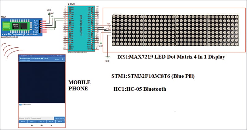
Since communication between STM32 and MAX7219 is based on SPI communication protocol, all we need is three pins from STM32 (Data, Clock, and Chip Select). The CS, CLK, and DIN pins of the MAX7219 IC board are connected to pins PA4, PA5, and PA7 of the STM32 controller.
Since Bluetooth is to be used for connection between STM32 and the Android device, the RX and TX pins of the HC-05 Bluetooth module are connected to TX1(PA9) and RX1(PA10) pins of the STM32 controller.
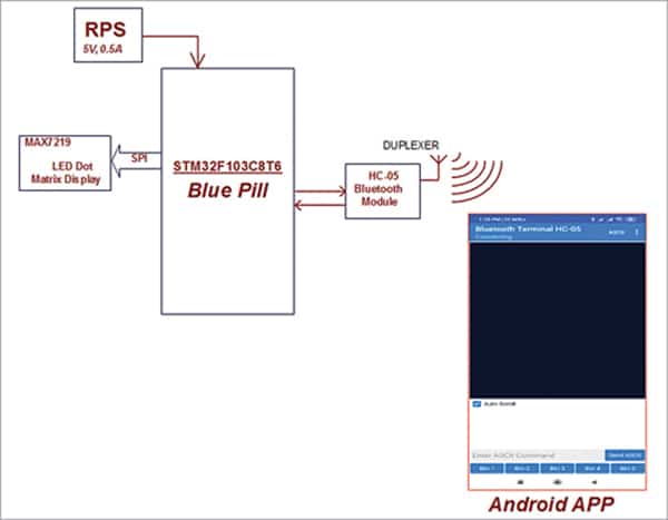
The block diagram in Fig. 7 shows interfacing of MAX7219 LED dot-matrix display with STM32 microcontroller using Arduino IDE and HC-05 Bluetooth.
Controlling the LED matrix through Android app
A dedicated app for Android based devices has been designed for this project. The layout of the app, which is already installed on a mobile phone (Bluetooth Terminal HC-05), is readily available in Google Play store from the free downloadable link https://play.google.com/store/apps/details?id=project.bluetoothterminal&hl=en_IN
Front view of the app is shown in Fig. 8.
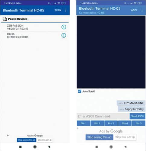
The app contains two modes—the HEX format and the ASCII format. Here we have used the ASCII format mode. In this mode we can send text, numbers, and any special characters to display, by default.
The moment we type these in the terminal app, the STM32 microcontroller immediately receives the information serially through Bluetooth. The received information is segregated and the text is shown on the LED dot-matrix misplay through SPI protocol. Remember, the end characters of text \r \n must be Enable in the ASCII mode, as shown in Fig. 9.
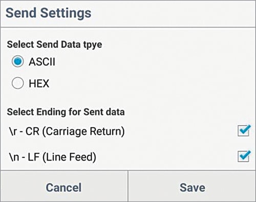
(EFY Note. The app utilises Bluetooth feature of the phone. Hence, necessary permissions must be given. Also, the HC-05 Bluetooth module must be paired with the device (phone), for which the default password is 1234.)
Software
The STM32 is just another microcontroller from STMicroelectronics. So, all the existing methods to program an ARM chip can be used for the STM32 board as well. One famous and commonly used IDE is the Keil ARM MDK, but we can also use IAR Workbench, Atollic TrueStudio, MicroC Pro ARM, Crossworks ARM, Ride 7, PlatformIO+STM32, etc.
What has made this board popular is its ability to be programmed with the Arduino IDE. This way people can get started and build projects with STM32 in no time, since many are already familiar with Arduino IDE, which is an easy-to-use programming language and has readily available libraries. So, here we will be using the Arduino IDE to get started with STM32.
The STM32 Blue Pill development board does not come with a bootloader to make it Arduino IDE compatible. However, this bootloader can be flashed into the STM32 board and then the micro-USB port can be directly used to upload the programs. Refer YouTube link to learn how to load bootloader.
Based on this tutorial you should be able to easily upload bootloader software. After successful completion you can use the onboard micro USB port.
Follow the steps below to download and prepare the Arduino IDE for use with the STM32 board.
| Parts List for 5v RPS | |
| Semiconductors: | |
| IC1 | – 7805, 5V voltage regulator |
| D1, D2 | – 1N4007 rectifier diode |
| Capacitors: | |
| C1 | – 1000µF, 25V electrolytic |
| C2 | – 100µF, 25V electrolytic |
| Miscellaneous: | |
| CON1 | – 2-pin connector |
| X1 | – 230V AC primary to |
| 12-0-12V, 500mA secondary | |
| transformer | |
Step 1. If you have not yet installed the Arduino IDE, download and install it from the internet. Make sure you select your correct operating system.
Step 2. After Installing the Arduino IDE, open and download the required packages for the STM32 board. This can be done by selecting File→Preferences.
Step 3. Clicking on Preferences will open the dialogue box shown in Fig. 10. In the Additional Boards Manager URL text box, enter the link below and press OK:
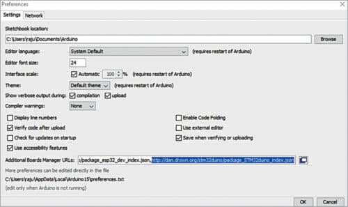
http://dan.drown.org/stm32duino/package_STM32duino_index.json
Step 4. Go to Tool→Boards→Board Manager. This will open the Boards Manager dialogue box. Search for STM32F1 and install the package that appears.
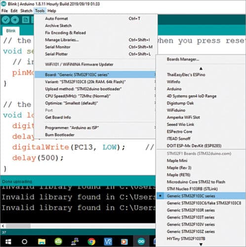
Step 5. After the package installation is done, go to Tools and scroll down to find the Generic STM32F103C series, as shown in Fig. 11. Make sure the variant is 64k Flash type, CPU speed is 72MHz; change the upload method to Serial.
Step 6. Connect the Micro USB board to the computer and check to which COM port the STM32 board is connected, using device manager. Select the same port number in Tools→Port.
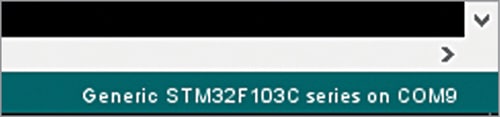
Step 7. After all the changes are made, check the bottom right corner of the Arduino IDE. You will notice the generic STM32F103C (Blue Pill) board is connected to COM9, as shown in Fig. 12. Now the Arduino IDE is ready to program the STM32 Blue Pill development board.
To operate the circuit the software program needs to be loaded into the internal memory of STM32. The program is written in Arduino programming language Sketch. Arduino IDE 1.8.11 is used to compile and upload the program. The project needs follwoing external header file for programming:
#include <MD_MAX72xx.h> :
The library implements functions that allow the MAX72xx to be used for LED matrices (64 individual LEDs), allowing the programmer to use the LED matrix as a pixel device, displaying graphics elements much like any other pixel addressable display.
Construction and testing
After uploading the source code mains.ino into STM32, complete wiring of the main circuit and connect 5V regulated power supply to it. After powering on, the circuit is ready to use.
For testing the project, upload the code mains.ino (written in Arduino IDE) to the STM32 microcontroller. Since the microcontroller does not have an Arduino bootloader preinstalled, we have to use an external device—such as the FTDI module or the USB-to-TTL converter with CP 2102 driver—to transfer the code by connecting one end of the module/converter to our laptop and the other to UART pins of the microcontroller.
To connect FTDI module, connect its VCC pin to 3.3V of the STM32 module, the GND pin to the GND pin of the STM32 module, and the RX and TX pins to the PA-9 and PA-10 pins of the STM-32 module, respectively.
An important step before transferring the code to the STM32 module is to set its boot mode to Boot-1. After this you can transfer the code serially from your laptop to the STM32 module.
For testing the project, you can use a normal adaptor having a micro USB for power supply instead of the 5V regulated power supply mentioned earlier. The mobile app can then be downloaded to connect to the HC-05 module. Now data can be input to check whether the project works as expected.
Download source code
Pamarthi Kanakaraja is an electronics hobbyist
Hi,
I am using STM32F407VET6 (STM32F407VET6 Arm Cortex-M4 core with DSP and FPU, black) Development Board. I am using following interface pins.
/************************* Matrix Display Pins *********************************/
#define CLK_PIN PB13 // or SCK PB13
#define DATA_PIN PB15 // or MOSI
#define CS_PIN PB12 // or SS
This is the only change, I have made to your code. No other change in the code. Code is compiling and uploading in the board. But I am getting random display. What could be potentially wrong, I am doing ?
Hardware is correctly wired and working for other applications. But not for Matrix LED display as mentioned above.
Thanks in advance for help
Best Regards,
Hardeep