


 This circuit of single-cell LiFePO4 (lithium iron phosphate) battery charger is based on an LM358 operational amplifier (op-amp) and a couple of inexpensive and easy-to-get components. It can be powered from any USB port or USB standard power supply adaptor. It does not use any difficult-to-handle surface mount device (SMD) or a miniscule chip.
LiFePO4 batteries are best known for their safety because of their extremely stable phosphate-based chemistry. Also, these newer type of lithium batteries are inherently non-combustible. Hence, these can withstand harsh conditions, be it freezing cold or searing heat. Even when subjected to hazardous events (collision or short-circuit), these do not explode or catch fire, thus significantly reducing the chance of any harm. The phosphate chemistry also provide a longer life to the batteries.
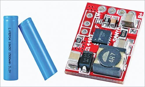
Single-cell LiFePO4 batteries are now within the reach of electronics hobbyists. These are also available pre-wired as LiFePO4 charger boards/modules from online vendors. Most such Chinese modules (1S/3.2V) are built around a 16-pin QFN chip—the TP5000 as shown in Fig. 1.

Circuit and working
Circuit diagram of the little LiFePO4 battery charger is shown in Fig. 2. The pnp transistor S8550 (T1) used in the circuit routes input DC supply to the battery through silicon diode 1N4007 (D1). Transistor T1 is controlled through LM358 (IC1) op-amp. The features of IC1 include low offset, common-mode input range to ground, and high differential input voltage capability. Green-colour LED1 acts as charging indicator while LED2 indicates a fully charged battery. LED3 works as power indicator but it also provides a fixed reference voltage to the inverting input pin 2 of IC1.
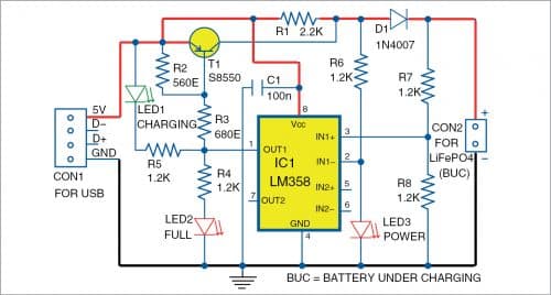
A 1.2-kilo-ohm resistor network (R7 and R8) is connected across the battery terminals. Output from the junction of this resistor network goes to non-inverting input pin 3 of IC1. Since the circuit is designed as a single-cell LiFePO4 (3.2V) charger, it is configured to give the recommended output of 3.6V.
When the connected battery’s (BUC) voltage is less than the threshold voltage, transistor T1 starts charging the battery and LED1 lights up to show that charging process is in progress. When the LiFePO4 battery’s voltage goes above a certain limit, charging current gradually decreases and finally T1 is switched off by IC1 to stop further charging. It happens just after the battery voltage reaches its expected 3.6V level, which is indicated by the glowing of LED2 and LED1’s turning off. Later, when the battery voltage falls below the threshold level, the charger restarts a new charging cycle automatically, if the battery to be charged is in the holder connected to CON2.
Construction and testing
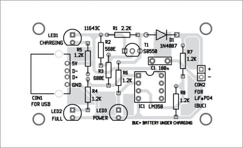
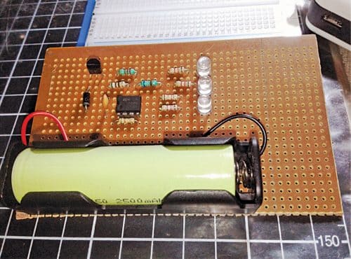
A small piece of perforated circuit board (or zero PCB) is enough for the construction of this circuit. A PCB layout for the little battery charger is shown in Fig. 3 and its components layout in Fig. 4. After assembling the circuit on a perforated board or PCB, connect a 5V DC supply across CON1. The author’s prototype is shown in Fig. 5.
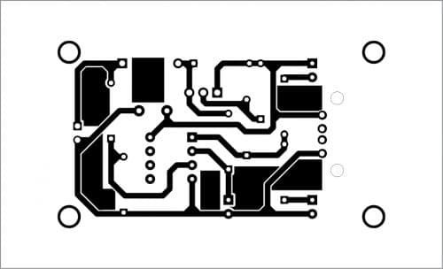
Download PCB and component layout PDFs: click here
Use of a good quality single-cell 18650 battery holder is recommended for lodging the battery securely. You can make a nice enclosure for the LiFePO4 charger in case you wish to use it on long-term basis.
After construction, power the circuit (without the LiFePO4 battery) with a stable 5V DC supply provided by a USB port, or a USB power adaptor, or a regulated lab power supply. If things are fine, you will see LED2 (full charge) and LED3 (power) glow. If you connect a voltmeter across the battery holder (CON2), it will display a DC voltage close to 3.6V. Now, when you insert the LiFePO4 battery into its holder, LED1 (charging) will glow but LED2 will go off.

Note. This circuit is simple but has some inherent limits as well, such as:
- Since all components’ values are critical, the circuit should be wired exactly as shown in the schematic.
- The author’s prototype was tested successfully with a 3.2V/ 2500mAh LiFePO4 battery and a 5V/700mA USB power source (having 3.6V maximum charging voltage and 250mA maximum charging current). You may need to change the values of resistors R2, R7, and R8 slightly to fine-tune the charger circuitry.
- Sometimes the charging and full charge indicators (LED1 and LED2) may not work as expected and a feeble (dim) glow may be seen. If that happens, just ignore it.
- IC1 op-amp is used here as a comparator without hysteresis. Often this causes the charging indicator to briefly bounce back and forth (random flicker), especially when the battery voltage level crosses (and re-crosses) the threshold region.
T.K. Hareendran is an electronics designer, hardware beta tester, author, and product reviewer