


Electromechanical relays are not reliable power switches. The electromagnet that they use needs to be energised till the plunger is at a specific position, thus consuming a lot of power.
Most of the IoT devices use the solid-state relay as they have no mechanical switching system and there are nearly zero failure points. At the same time, solid-state relay save a lot of power as they do not require power the whole time. You can even turn the power OFF when switching is completed; it only requires power while switching ON the circuit.
Solid-state relays are also very silent and do not produce noises while switching unlike other switching systems.

Solid state relays come with a lot of benefits and should be readily implemented. But their price is a major barrier. Electromechanical relays approximately cost Rs 60 while solid state relays cost more than Rs 800. In order to bring the benefits of solid state relays to more people at an affordable cost, I have simplified its design that can be used with this highly reliable IoT project. This IoT system is operated by Alexa. So let’s begin our exploration with the shopping of the following components.

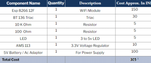
Bill Of Material
Designing
First, design the solid state relay by eliminating the mechanical switching system that can be controlled using a small DC current. Despite having voltage as low as 2V to 5V, it can drive and switch the AC appliance and circuit having voltage of 22OV. But how can it switch the 220V AC appliance while using only a 3V switch? For that, isolate the two circuits electrically and at the same time, couple the two circuits using an optocoupler chip. An optocoupler coupler is basically a device with LED and a photodiode coupled together. This allows the two different circuits to share each other’s signals using light. Both do not need to be electrically connected; one circuit sends a signal to another to switch without any electrical connection. As the optocoupler is based on light which travels the fastest among all other waves, it’s another advantage of optocoupler.
Cost Optimisation
An optocoupler costs Rs 30 to 80. Because the device is a combination of photodiode and LED packed inside a chip, you can simplify your design with LDR and LED coupling instead of optocoupler
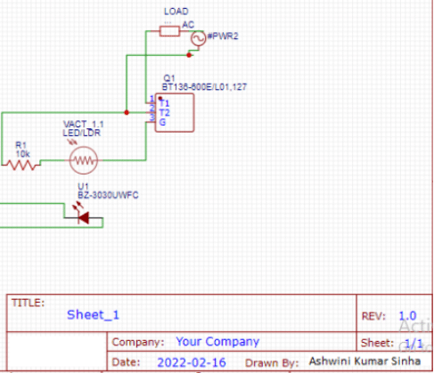
You can use TRIAC and LDR with a resistor to make the solid state relay. When an LED is coupled with the LDR, then the resistance of the LDR connected to TRIAC falls gradually and as a result of the opening of gate, the flow of AC current gets allowed that was blocked by the gate of TRIAC in the IDEAL switch off state .

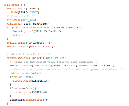
Coding
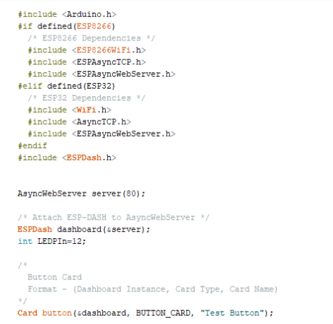
For the IoT-based switching system, we have used the ESP 12 F and created a firmware that helps us to connect with our WiFi network.
For the UI to control, trigger and switch our solid state relay, we have used the ESP Dash library that helps us to give a dashboard with buttons and other UI cards for triggering and setting various actions of your choice. Use the button to drive the led that is coupled to the LDR to AC circuitry.
To program the ESP, you need to set up the Arduino IDE and install the required libraries.To know the process of installation of ESP board to Arduino IDE, refer to the ESP RGB led light article.
Then create the code for initialising the library and define the pin to control the coupler LED. After setting the SSID and password of the home network to which you want your relay to connect, create a setup function. To start the WiFi, check the connection status and host the web UI of your relay. Then in loop function, check and update the action of the button on web UI .
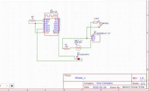
Connection
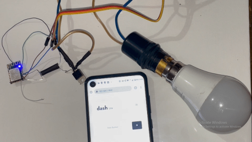
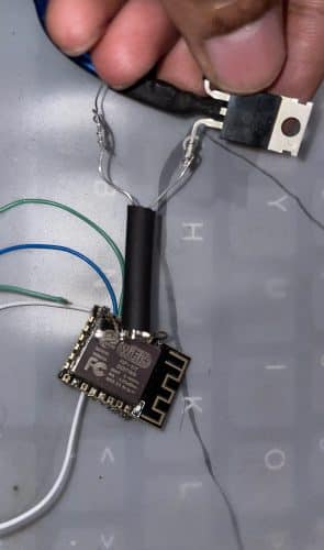
Connect the components as shown in the circuit diagram to insulate the connection with the heat sink tube. Now couple the LDR and LED in such a way that the outside light will not affect the LDR but only LED.
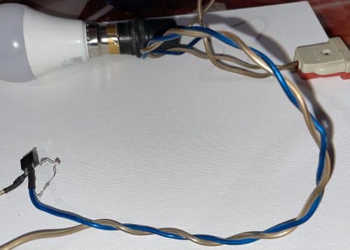
Here, I have used the same heat sink tube. Now add the AC appliance/load that you want to control. Here, I am using a light bulb but you can use a fan, lamp etc. Next use any 5V DC adaptor with AMS 113 voltage regulator to regulate 3.3V for ESP. Power the ESP12 board and fix everything inside. Your IoT solid state relay will be ready for use. You can switch your light and fan wirelessly without making any “tick” noise that mechanical relays make.
Testing
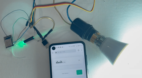
Now connect the device and search its IP address on the phone that you got from ESP in the serial monitor. Save it for future use. You can power the device, plug the circuit to the AC socket and then search the IP address on the web browser. When you get the web UI with a button, you can toggle the button ON/OFF of the solid-state relay for wireless switching.
