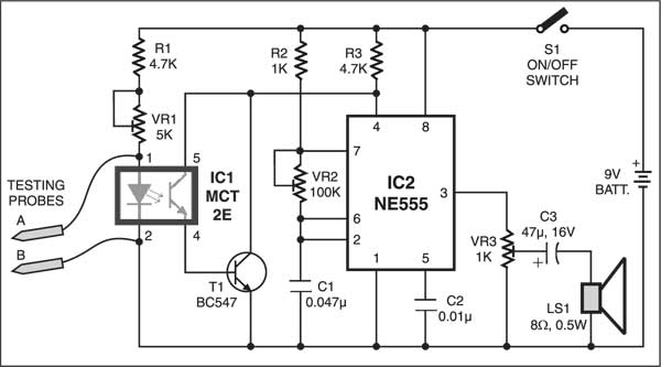
 Continuity testing is the act of testing the resistance between two points. If there is very low resistance (less than a few Ωs), the two points are connected electrically, and a tone is emitted. If there is more than a few Ωs of resistance, than the circuit is open, and no tone is emitted. This test helps insure that connections are made correctly between two points. This test also helps us detect if two points are connected that should not be. The circuit presented here can be used as a low resistance continuity tester of low-resistance paths such as PCB tracks, small coils, intermediate frequency transformers (IFTs) and low-resistance transformers. However, you can’t check semiconductors with this tester. The tester works off a 9V battery.
Resistance Continuity Tester Circuit
The tester is built around optocoupler MCT2E (IC1) and timer IC 555 (IC2) that is wired in free running mode. Optocoupler MCT2E is used here as a continuity sensor. Testing probes A and B are connected to pins 1 and 2 of optocoupler IC1. The phototransistor inside the optocoupler is connected to transistor BC547 (T1) to form a Darlington pair, which improves the performance of the circuit.

When the probes are not shorted, the LED inside the optocoupler glows and the Darlington pair conducts to keep reset pin 4 of IC 555 at ground level and thus no sound is produced.
When probes are shorted via a low resistance, the LED stops glowing and the Darlington pair doesn’t conduct. As a result, reset pin 4 of IC2 goes high to activate the loudspeaker, which generates a sharp audio tone.
To minimise the current through IC1 when probes are not shorted, adjust VR1 until the circuit just stops sounding. The output tone and loudness can be varied by adjusting presets VR2 and VR3, respectively.
The article was first published in April 2004 and has recently been updated.


hey it don’t work, I wish you guys would check out the circuits you present, a big waste of time
Kindly recheck the connections and try again