
 Digital compass and protractor are two of the most basic tools for specifying directions and measuring angles. But sometimes it is difficult to get accurate angle measurement for certain structures and geometrical shapes using these traditional tools, for example, the angle between two adjacent walls.
So I thought of developing a digital protractor to make the work a bit easier. I came up with two different methods to make a digital protractor: first by converting the MPU6050 sensor data into angle, and second by converting stepper motor rotation into angle. The second method is explained here.
For this project, we need the following components:

- Arduino Pro Mini
- ULN2003A module
- 28BYJ stepper motor
- Two pushbutton switches
- OLED display (I2C interface)
- 5V battery
- Jumper wires
The circuit diagram of digital protractor using stepper motor is shown in Fig. 1. All the positive terminals (+) should be connected to 5V supply and negative terminals (-) to common ground (GND). Switch S1 is used for rotating stepper motor in clockwise (CW) direction and switch S2 for counter-clockwise (CCW) direction. A five-wire, unipolar stepper motor (28BYJ) is connected across the ULN2003A motor driver module.
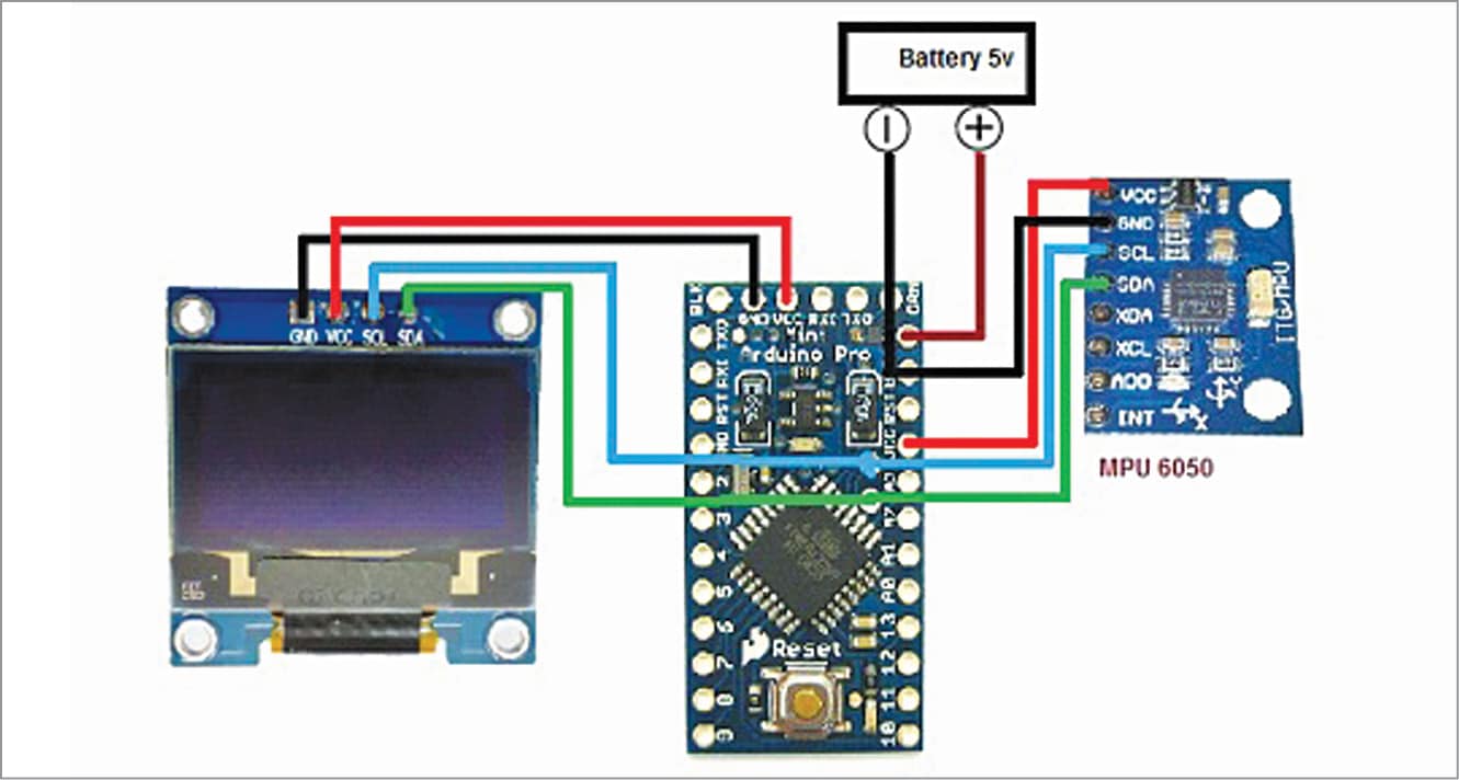
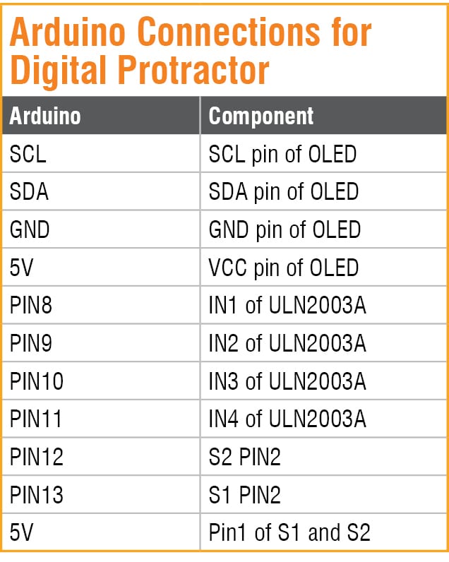
Arduino Pro Mini connection details with the components are given under Table 1.
Coding
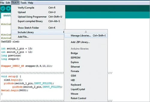
The firmware (digital_protractor.ino) for this project is written in Arduino programming language. First, add relevant software library to Arduino IDE from Include Library as shown in Fig. 2.
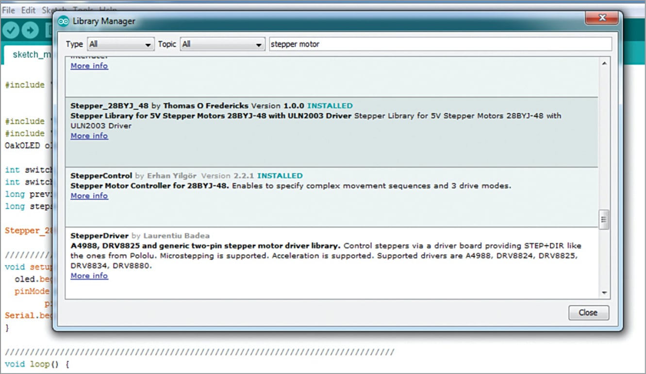
Install the ‘28BYJ_48’ libraries as shown in Fig. 3. After the successful installation of the required libraries, start Arduino coding.
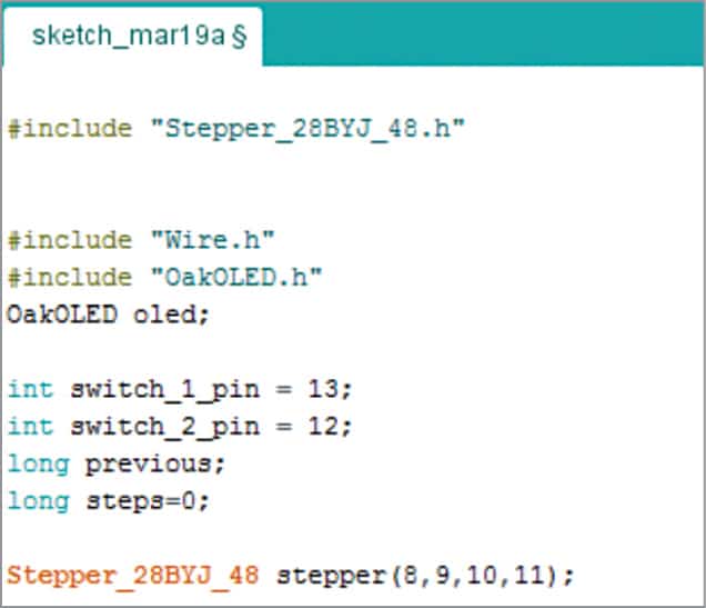
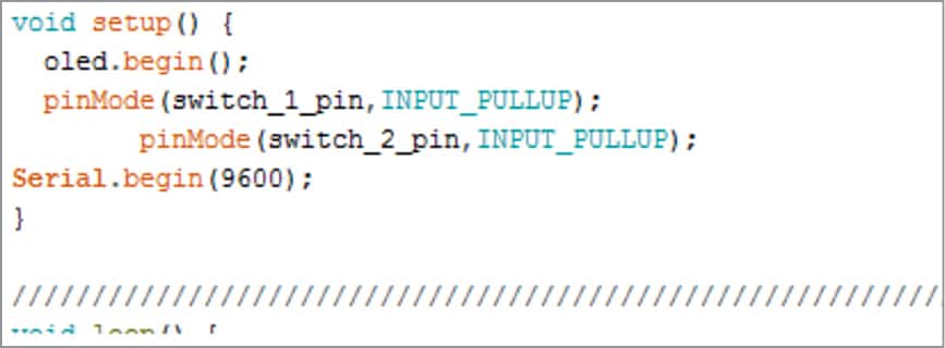
Include stepper motor libraries and declare the variables needed to store different values as shown in Fig. 4. After this create a setup ( ) function, which is shown in Fig. 5.
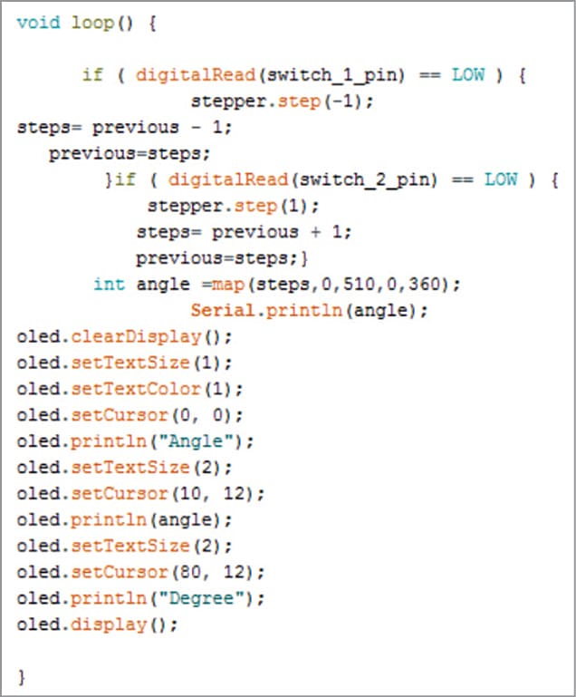
Next, create a loop function and include ‘if ( ) condition’ to check the state of the pushbutton. When if ( ) condition in code says true, stepper motor moves one step and stays there until the condition turns false (which happens when the switch is not pressed).
To measure the angle, calculate the steps moved by the motor. To do so, I have created a step variable that will store the previous value of stepper motor and go on adding one by one as the motor moves. Are you confused? Let me explain it in simple words.
Suppose the initial value of the step variable is zero. When the motor moves one step, its value will change to 0+1. This value is assigned to another variable named ‘previous,’ so the previous value is now 1; when the motor moves another step, the new value becomes previous value +1. In this way, each time the motor moves a step, the number of steps automatically get added. For example,
Step = 0+1
Previous = 0
Step = 1+1
Previous = 1
Step = 2+1
Previous = 2
This is how the steps of motor are calculated.
After this, we need to convert the steps of motor into angle by using a map ( ) function.
map (min steps, max step, min angle,
max angle)
The magic happens here! When we put this code in loop function, the steps automatically get converted into angle.
In order to map the angle value of stepper motor, we need to know the maximum number of steps it takes to complete one full rotation. In this project, stepper motor takes 510 steps to complete one full rotation. The same is defined in the code as shown in Fig. 6.
Now we are done with the coding part. So let’s construct the digital protractor as shown in Fig. 7. The principle of protractor needle movement is shown in Fig. 8.
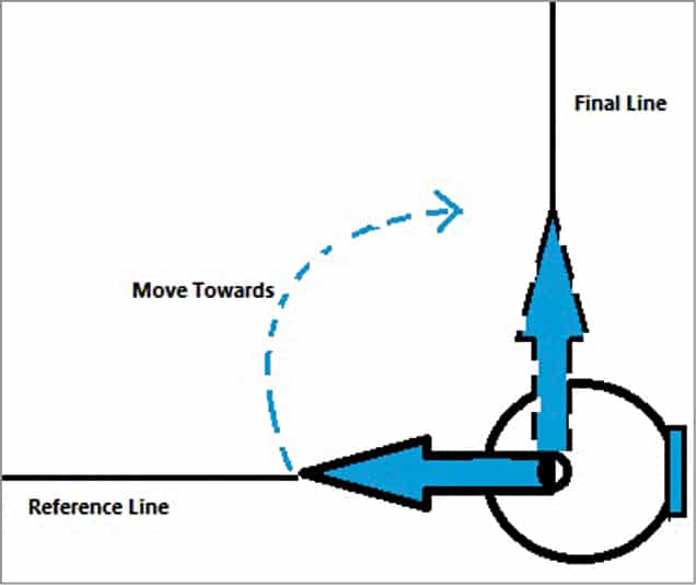
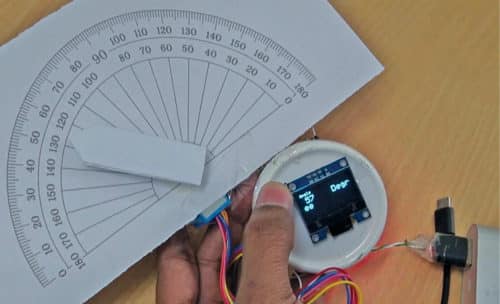
The digital protractor can be calibrated by using a protractor mapped on a piece of paper as shown in Fig. 9. A fixed needle or pointer is to be attached on the stepper motor parallel to 180-degree angle line of the protractor, which acts as reference line. This needle can be placed on the bottom side of the protractor during calibration. A moveable needle is to be attached to the shaft of the stepper motor that is used for angle measurement.
The moveable needle can move in clockwise or anti-clockwise direction with respect to the fixed reference needle. The angle between the reference needle and moveable needle is displayed on the OLED display.
When the moveable needle rests on the reference line on the left side, the angle read is 0. When you press button S1, the moveable needle moves in clockwise direction until it reaches the desired position (the final line of angle).
Testing
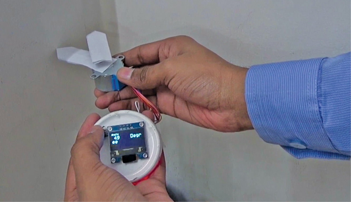
Double check all the circuit connections, as any mistake might fry your costly components. Then power on the Arduino board and ULN2003A motor driver module. Press switch S1. As the needle starts moving clockwise, the angle moved with respect to the reference line is shown on the OLED display. If you press switch S2, the stepper motor will start moving in opposite direction, and angle value shall start decreasing, which can be seen on the OLED display.
This protractor is more useful for measuring the angle between adjacent walls and solid structures, links and joints as it is very hard to put a conventional measuring device in such places.
Download Source Folder
Ashwini Kumar Sinha is an electronics enthusiast and tech journalist at EFYi.