


 Low-current measurements are generally not reliable due to resolution of the measurement devices, which are mainly meant for measuring a current of a few hundreds of milliamps to a few amps. This circuit can measure currents of the order of 1mA with better accuracy, and therefore can be useful for DIY projects.
Circuit and working
The circuit is built around Arduino Uno board (Board1) and a 16×2 LCD (LCD1) display. When current passes through a resistor, a voltage drop occurs across the resistor, which is proportional to the current passing through it. The circuit uses this fact to measure the current through the resistor or any other load.
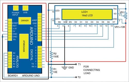
The current is measured by this circuit using the voltage drop across the sense resistor R1. The analogue reference voltage is changed to internal 1.1V reference for better resolution.
Connect the test probes in series with the load. When the load is powered (switched on), it consumes current, which flows through resistor R1 and generates a voltage drop across it proportional to the load current. The voltage is given to the analogue pin A0 of Board1.

The Arduino is the brain of the circuit; it calculates the current based on the ADC value and displays it on LCD1. The current at the analogue pin A0 should not go beyond 100mA. If it does, the “over range” alert message is displayed on LCD1 whenever the current goes beyond the limit.
Arduino Uno is a popular open source microcontroller development board based on ATmega328P microcontroller. It has 14 digital input/output (I/O) pins of which six can be used as PWM outputs, and six analogue inputs, a 16MHz crystal, USB connector, power jack, and ICSP header. It comes with preloaded Arduino bootloader in ATmega328P chip.
Construction and testing for Milliamp Meter
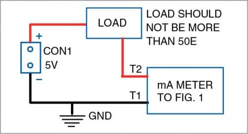
You can assemble the circuit on a PCB or breadboard. Arduino can be powered by an external 9V battery or 9V, 500mA adaptor. Use test probes for better accuracy and low attenuation. To connect the load across terminals T1 and T2 for mA current measurement, refer the wiring diagram shown in Fig. 2.
Upload the source code (mA_meter.ino) to Arduino Uno (Board1) before using the circuit.
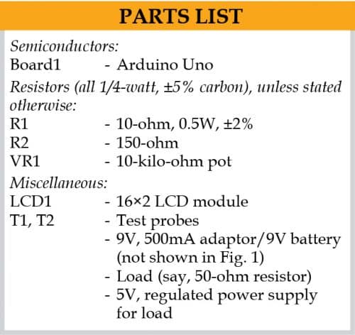
Note. This circuit measures low currents from 1mA to 100mA only. Do not reverse the polarity of the cable as it may destroy the Arduino board. There may be tolerance in the readings due to the parasitic elements in the PCB. Resistor R1 should be a precision resistor with tolerance within 2% and minimum wattage rating of 0.5W.
Download Source Code: click here
A. Samiuddhin, a circuit designer, is B.Tech in electrical and electronics engineering. His interests include LED lighting, power electronics, microcontrollers, and Arduino programming.
