


 Milliohm meter is used to check low resistance of connecting wires. It can deduce the resistance of thick wires, condition of contacts and the length or quality of wires. Although the continuity can be easily checked using a continuity tester, the exact condition of the circuit cannot be assessed without proper measurement. For example, a switch in good condition will have very low contact resistance, where as, if the switch is in bad condition its resistance would be much higher even though it may pass the continuity test.
The quality of wires can also be assessed. Broken strands can significantly increase the resistance on the milliohm scale. Commercial copper wire has resistivity as follows:
![]() ohm metre, at 20°C
ohm metre, at 20°C

So, a 0.5mm diameter wire having a length of 10 cm would have a resistance of ~9 milliohm. This is calculated using the following standard formula:
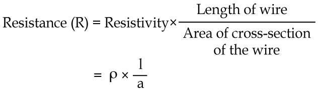
You can use this relation to calculate resistance of different metals. The resistance of ordinary connecting copper wires in electronic circuits is of the order of milliohms. To measure it, a millohm meter is required. The knowledge of the resistance of a certain wire of unknown length can be used to deduce its length or vice-verse. Knowing the length of the wire in certain winding of a transformer or a rotor, and assuming certain standard winding configuration, one can deduce the approximate number of turns in that winding. All these require a measurement of the resistance of the wire which is of the order of milliohms and above.
The circuit described here has a minimum resolution of 50 milliohms and a maximum range of 10 ohms. These limits seem to be adequate to deal with ordinary conducting wires. The operation of the circuit is based on the standard technique; pass a known fixed current through the resistance (Rx) and measure the potential drop across it.
Since the resistances being measured are extremely small compared to the other electronic standards of hundreds and thousands of ohms, a fixed-precision resistance is used in series with the supply voltage to get a constant current. A 50mA constant cur-rent is obtained by using a resistance of 100 ohms and a supply of 5V. This will be used to measure a maximum resistance of 10 milliohm which is 10000th of 100 ohms and so its presence in the circuit is negligible compared to the 100 ohms resistance. Thus the current remains sufficiently constant throughout any range.
The voltage-drop across the unknown resistance (Rx) is measured using op-amp TL081, which has been configured as a high-gain non-inverting DC amplifier with a gain of 100 = (Rf/R1 + 1). The voltage drop across Rx is multiplied by 100 and presented to the meter by the op-amp.
The meter’s resistance has been assumed to be 700 ohms, so an additional 500 ohms is required to properly calibrate the instrument. This can be done using preset VR2 in series with the meter as shown in the circuit diagram. The offset of the circuit can be removed by shorting the test leads with a thick copper wire and setting the set-zero potmeter VR1 for zero deflection in the analogue multimeter. The diodes (D1 and D2) in parallel to the analogue meter are for its protection from over-voltage.
Finally, the voltage output of the op-amp can be summarised using the relationship for the gain of non-inverting op-amp configuration into a simple relation as:
Vo = Iconst Rx (Rf/R1+1)
where Iconst is the selected constant current from any particular range given here as V/R= 5V/(500ohms, 1k, 10k or 100k) amps. Rf and R1 are given in the diagram. IC CD4066 (IC2), an analogue switch, is used here to exhibit zero meter deflection when no resistance is connected across the test terminals.
For measuring the low resistance of copper wire (Rx), connect it at appropriate terminals. Select the particular range in such a way that resistance value is indicated on the meter directly.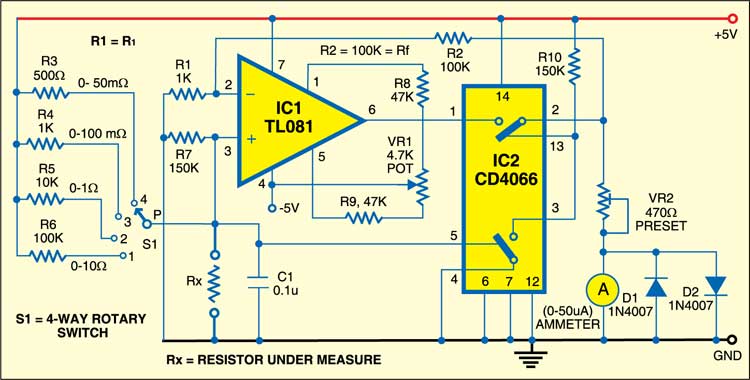

Good day.
To whom it may concern
I just wanted to know if it’s possible to use a LM358 Op-Amp instead of the TL081.
I realize there will be no balance control. But I was just wondering, as I have a lot of those
LM358 Op-Amps in stock.
Thank you for your support on this matter
R.Strydom
Yes you can try with LM358, though we have not tried with it.
The operation of the CD4066 analog switch is not clearly explained. It would be appreciated if the operation of the circuit is edited to explain more clearly what happens when the switch is closed or opened.
Thanks for the interesting article.