


 Many times we wish to stream the same song on multiple locations simultaneously. Audio streaming can be done on all speakers while connecting a single audio source to another speaker wirelessly. We can use a Multi-room Audio system to do this.
But multi-room audio casting devices are quite expensive. They work on Wi-Fi and sometimes face a latency issue. Devices like Airplay M U2Stream services range from Rs.7k-Rs.20k.
This DIY project uses a hack and achieves multi-room audio streaming at an economical cost.

Multiple transmitter chips are stacked with a BT receiver chip. This chip is connected to a phone or laptop from which the original audio source is played. Upon receiving the audio signal, the BT chip transmits it to multiple transmitters. These transmitters are connected to other Bluetooth speakers, which stream the original audio. Thus audio latency will not take place and the original audio will be played simultaneously.
All these audio devices can be controlled from one casting device. Since the range for Bluetooth is only 100-200 meters, the distance between the speaker and receiver should technically be within this range. However, this range can be expanded in this project by using an audio repeater device. The audio repeater acts as an intermediate device between the main Bluetooth and target devices. It first connects to Bluetooth from the main source and then connects to the target device for audio transfer.

KCX BT Emitter is a good transmitter chip, however, any other relevant chip in the market can also be used.
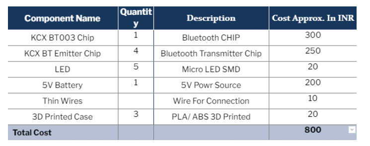
Bill of Material
Designing Multi-Room Audio System
The original audio is obtained from the phone/laptop that connects to the main streaming device over Bluetooth and then is sent to multiple BT transmitter chips. From these transmitter chips, the audio is streamed over multiple speakers.
The repeater device should be set up between the source and target devices. The repeater device will first connect to the main Bluetooth audio source and then using the emitter chip will repeat the connection to the target speaker, thus extending the range of BT audio transmission.
Main Multi-stream Device
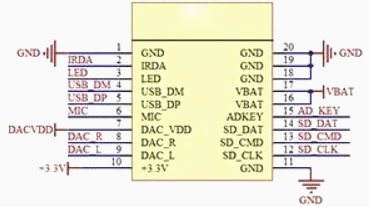
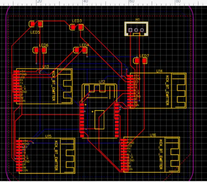
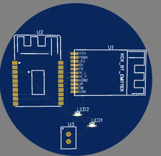
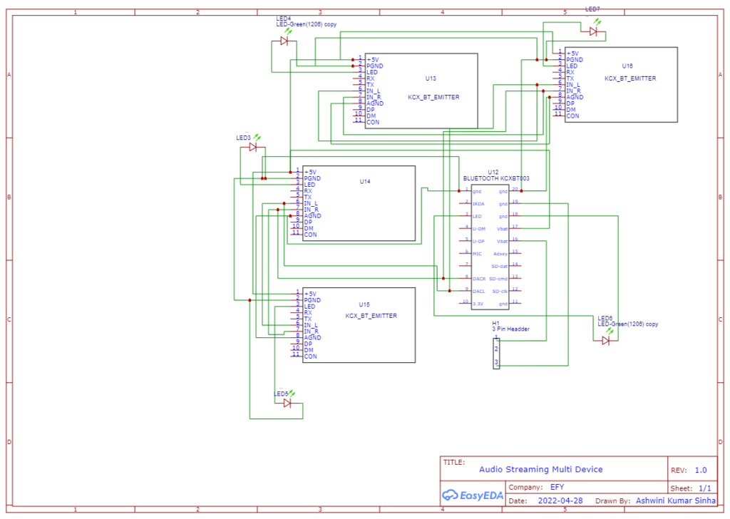
For the main multistream device, the number of BT emitter chips is directly proportional to the number of connectable devices. The repeater can add up to 4 more devices. The KCX BT emitter chip is used for reference. From the datasheet and figure 3, the KCX BT003 chip is used for connecting and receiving the audio from the original source(phone/laptop, etc.). The pinouts of the KCX BT 003 chip give the DAC, audio output pins.
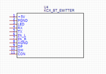
To combine multiple BT Emitter chips, the L input of the chip has to be connected with all the other BT emitter chips.
This should be further connected to the output DAC L pin of the BT KCX 003 chip.
The same process should be followed for the R pins, connecting them to the DAC R pin.
The Vcc of all the KCX BT emitters is connected to the Vbat pin of the KCX BT 003 pin header, for powering the chip.
The same process is repeated for the other GND pins of all chips.

Multi-Room Audio System PCB
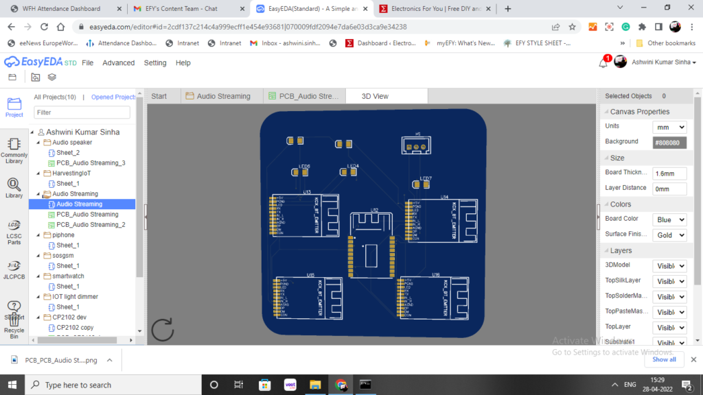
If a PCB is needed, the circuit design can be converted into PCB by downloading the Gerber file attached. The shape and size can be customized, here a round rectangular shape of PCB is chosen. The right footprints of other components used should be set in PCB, eg. LED bulb, etc.
Here the footprints of the SMD LED bulb and power header are set. The power header powers the device. After all the connections are thoroughly checked, the PCB can be sandwiched accordingly. The PCB design is shown in figure 6.
The Gerber file can be exported to the manufacturer to order the PCB board online. Relevant layers can be selected. Aluminum generally costs less. The rate by the manufacturer also varies with respect to the color of the PCB. Do not forget to select the appropriate thickness needed.
NOTE:- The PCBs are still in the shipping process. So testing could not be done using a PCB. However, the PROJECT is FULLY TESTED without the PCB by connecting individual chips and components.
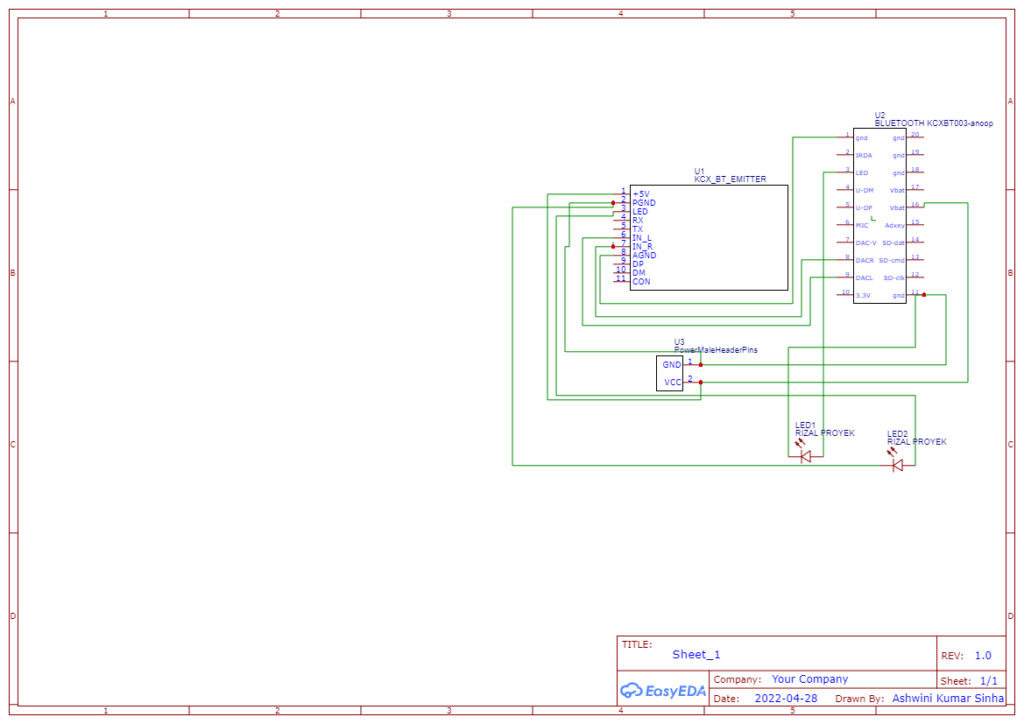
Audio Repeater Device
An audio repeater is needed only when the streaming exceeds the Bluetooth range of the device. To make an audio repeater, the KCX BT emitter chip and KCX BT 003 chip should be connected as in the following circuit diagram. (Refer to figure 11)
Multi-Room Audio System Connection
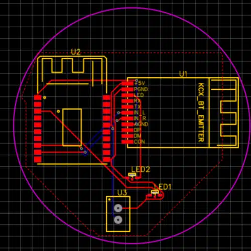
If the device is not being made into a PCB, refer to figure 12 for the proper connection of the components.
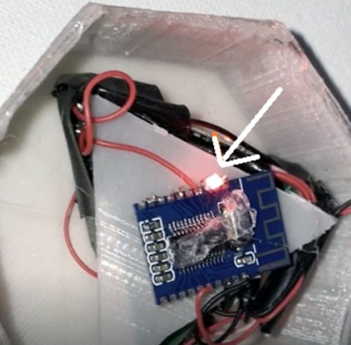
The chips are soldered together with thin wires, but because these are SMD chips, proper micro-soldering has to be done. The LED indicator is soldered to the KCX BT 003 chip. The SMD LED is used here, however, any other relevant can also be used. A small solder is placed at the terminal.
The complete circuit now has to be powered. This can be done using a USB connection or any 5V battery with a switch.
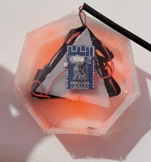
Here a hexagon-shaped case is used for placing the components. The case has been printed using a 3D printer.
The LED will indicate the power of the chip and its connection with Bluetooth devices and speakers. An acrylic cover on the top of the casing is used to indicate if the audio is being streamed.
The BT Emitter chips are connected in a triangular pattern, such that the LED indication of the Emitter chip is visible. The KCX BT 003 chip is fixed on top of the triangular pattern, to receive the audio over Bluetooth and transfer it to all the KCX BT emitter chips.
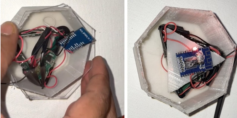
A transparent acrylic sheet of the same shape is cut and closed over the casing. This helps us view the LEDs from all the chips to know their relevant status.
Testing Multi-Room Audio System
The device should be powered and connected to the Bluetooth receiver chip. It should be paired with the KCX BT 003 chip for the audio signal to start playing over.
When multiple Bluetooth speakers are brought near to this device and powered on, the speaker will automatically connect to the device and start playing audio simultaneously.
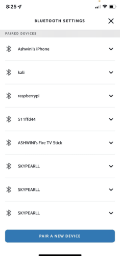
Figure 15 is a screenshot of the Alexa app that scans for Bluetooth. The multiple similar names of Bluetooth are devices that are ready to stream audio to multiple speakers at the same time
An affordable multi-speaker audio streaming device is now ready.
If you face any issues while making your own audio streaming device, please feel free to ask in the comments below.
There are some other Interesting Audio Streaming Projects…
Sir, Thank you for the cost effective and useful project.
The Bill of Material listed shows FM audio transmitter and RDA5807M FM receiver. But I can’t see any reference in the description or schematic.