


Noise is a serious environmental problem that affects us in our daily life. There is scientific evidence supporting that noise exposure can cause hearing loss, hypertension, heart disease, annoyance, sleep disturbance and decreased performance in schools. Sound-level indicators like the one presented here can help address this problem. This noise level alarm monitors the sound level and indicates through an LED when the level is above the preset value.
Noise level alarm circuit and working
Fig. 1 shows the circuit of noise-level alarm. The circuit is built around three BC550 npn general-purpose transistors (T1 through T3), electret microphone (MIC1), two LEDs (LED1 and LED2) and a few other components.


The sound is captured by microphone MIC1 and amplified by first-stage high-gain transistor T1. Trimmer potentiometer VR1 is used to adjust the threshold level. the signal is amplified again with second-stage transistor T2. This amplified signal is rectified by diode D1 and the charge is stored in capacitor C10. Diode D1 should preferably be a small-signal Schottky diode such as BAT81, BAT82, BAT83, BAT85 or better. You can use 1N4148 and 1N914 also but the signal from the input should be stronger.
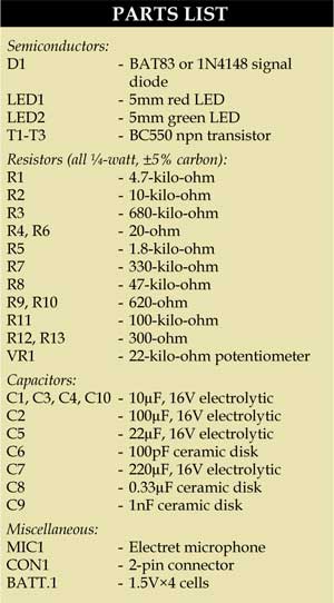

When the voltage across capacitor C10 is high enough, transistor T3 conducts and LED1 glows to indicate that the sound level is higher than the set level. LED2 indicates power supply is available to the circuit.
Transistors T1, T2 and T3 should be high-gain type, such as BC550C, BC109C and BC108C. For powering the circuit, you can use 6V from four AA-size batteries or 6V from a regulated wall adaptor.
Construction and testing
An actual-size, single-side PCB for the noise level alarm indicator is shown in Fig. 2 and its component layout in Fig. 3. After assembling the circuit on a PCB, enclose it in a suitable case. Fix LED1, LED2 and potentiometer VR1 on the front panel.

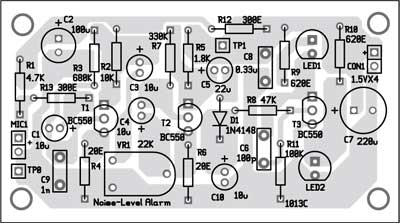
Download PCB and component layout PDFs: click here
After connecting the 6V power supply to the noise level alarm circuit, set the desired threshold of sound and adjust VR1 to the point where LED1 starts glowing. For that, switch on radio or TV set and set its volume to a level where you want the warning to start. Now adjust potentiometer VR1 to the point where LED1 starts glowing.
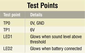
To test the noise level alarm circuit for proper functioning, check correct input supply at TP1 with respect to TP0. LED2 also indicates the same. LED1 glows when the sound level is above threshold, which can be simulated with a radio or music system.
The author was a researcher and assistant professor in Technical University of Sofia (Bulgaria), and a lecturer and expert-lecturer in Kingdom of Morocco. Now he is working in the private sector in Bulgaria


output not come for this circuit……
my diploma projects
First, check the voltage across TP0 and TP1. You should get around 6V DC. Check proper connections in the circuit. Vary VR1, speak or clap infront of the mic and then check the status of the LEDs.
I want to see how to make this project. … If possible pls send it fast
why my circuit works for only few seconds,after then red led starts getting dim.?
Transistors T1, T2 and T3 should be high-gain type, such as BC550C, BC109C and BC108C. These are 3 different but you mention that T1 to T3 BC550C. Please clear all 3 are different or same.
I would like to get your help in my project
What is the relation between sound and threshold? How can I determine which VRI value responds to sound in db?
Generate some noise or sound infront of the mic, slowly vary VR1(22K) till the LED begins to glow. Threshold level is minimum sound level below which LED will not glow. Please refer to standard sound level chart in dB.