


 Autonomous systems, especially in robotics, are transforming industries by performing complex tasks efficiently. Obstacle avoidance is crucial for autonomous robots, allowing them to detect obstacles in real-time and reroute themselves to avoid collisions. By integrating ultrasonic sensors and Arduino, this robot can autonomously navigate various environments. In this guide, we’ll provide a detailed step-by-step process to build an Obstacle-Avoiding Autonomous Car Robot using Arduino!
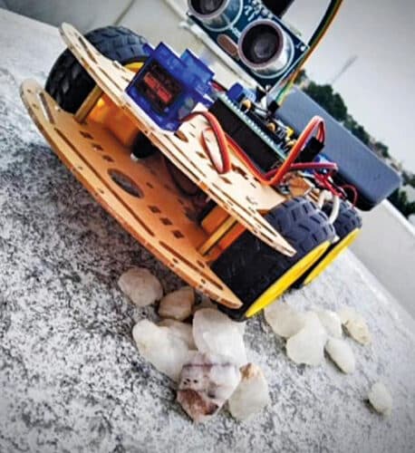
This project presents an Obstacle-Avoiding Robot designed with built-in intelligence that navigates autonomously using an algorithm. The robot detects and avoids obstacles, allowing it to move efficiently in unknown environments without human intervention. This flexibility makes obstacle-avoiding robots ideal for dynamic settings, enhancing their overall efficiency. Below, we’ll show the prototype and explain the design process in detail.

| Bill of Material |
|
1. Arduino Uno R3 -1
2. Motor driver shield -1 3. Wheels -4 4. DC gear motors -4 5. Servo motor -1 6. Ultrasonic sensor -1 7. Sensor stand -1 8. Lipo battery -1 9. Acrylic sheet -1 10. Male and female jumper wires |
The ultrasonic sensor is vital for this project. It transmits ultrasonic signal bursts at 40 kHz, which bounce back when an object is detected. The sensor generates high-frequency sound waves and analyzes the echo received to measure the distance to obstacles. By continuously calculating this distance, the ultrasonic sensor enables effective navigation for the Obstacle-Avoiding Robot, ensuring safe and efficient movement.
After an obstacle detection, the car changes its direction by making an autonomous decision. It can measure the distance between itself and surrounding objects in real time.
Software
The program is written in Arduino programming language Sketch. Arduino IDE 1.8.11 has been used to compile and upload the program in the prototype. The project needs various libraries, which have to be included in the external header file for programming.
For uploading the source code ARDUINO_OBSTACLE_AVOIDING_CAR.ino into Arduino Uno board, connect the Arduino board to desktop/laptop using a USB cable. Next, select the board and port and upload the source code.

Construction and Testing
First of all, upload the source code into the Arduino Uno and follow the steps mentioned below to assemble the robot.
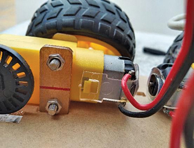
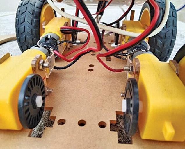
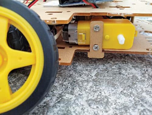
Step 1. Assembling the chassis (see Fig. 4, Fig. 5, and Fig. 6):
- Solder the wire to positive and GND of the DC gear motors
- Attach the DC gear motors to the bottom of the chassis
- Attach the wheels to the DC motors
Step 2. Mounting the components:
- Screw the Arduino onto top chassis
- Then plug the motor driver shield into Arduino
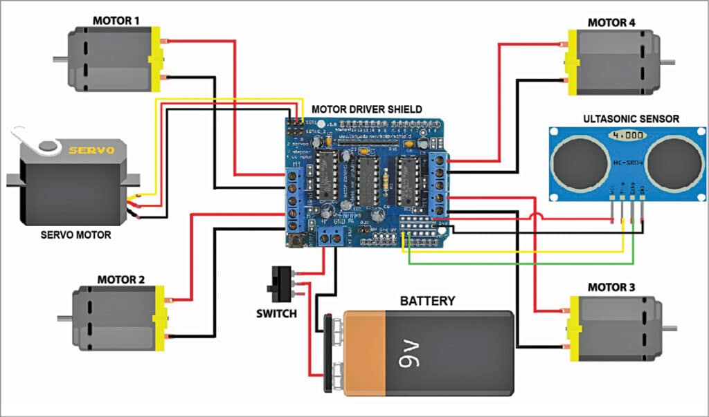
- Connect the motors to correct pair of terminals—the front motors to front terminals of motor shield and the rear motors to rear terminals of motor shield
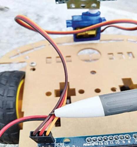
Fig. 10: Servo setup
Step 3. Setting up the servo:
• Attach the servo on top of the chassis
• Plug the servo into Servo 1 (SER1) header pins on the shield
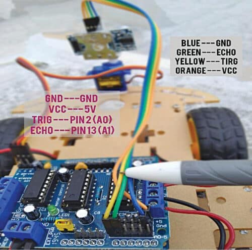
Step 4. Preparing the ultrasonic sensor: (Fig. 11: Sensor connections)
Place the ultrasonic sensor on the servo using the sensor stand. Then plug four wires into the sensor using female jumpers. Next, connect sensor to Arduino Uno as described below:
GND→GND
Vcc→5V
TRIGpin 2 (AO)
ECHO→pin 13 (A1)
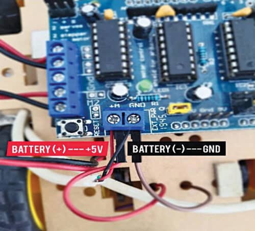
Step 5. Powering the robot:
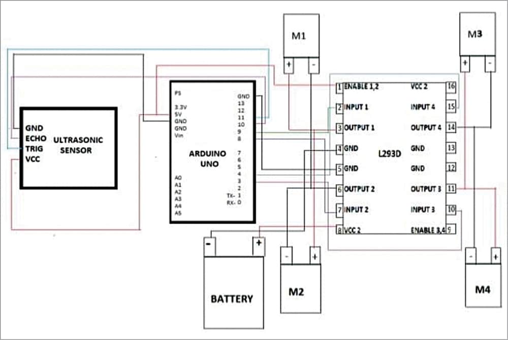
Connect the Lipo battery to the L293D motor driver as follows:
Lipo battery (+)→+12V
Lipo battery (-)→GND
The obstacle-avoiding robot is now ready! It can be used for such applications as:
- Mobile navigation systems, military and law enforcement, search and rescue, and forest conservation.
- For household work like automatic vacuum cleaning.
- With proper programming, for weightlifting and auto parking assistance.
Future Enhancements
- Machine Learning Integration: Implement machine learning algorithms to enhance decision-making processes for more adaptive navigation.
- Additional Sensors: Incorporate infrared or LIDAR sensors for improved obstacle detection and depth perception in complex environments.
- Remote Control Features: Add Bluetooth or Wi-Fi modules for remote monitoring and control, allowing users to intervene when necessary.
- Advanced Navigation Algorithms: Develop algorithms that allow for better path planning and efficiency, especially in crowded or dynamic environments.
Conclusion
In conclusion, the Obstacle-Avoiding Autonomous Car Robot exhibits robots’ amazing potential for navigating complicated settings without human involvement. This project uses ultrasonic sensors and Arduino technology to provide a hands-on introduction to the basics of autonomous navigation. The obstacles encountered during development can be addressed with careful calibration and changes, and future developments provide exciting prospects for additional innovation. As technology progresses, the capabilities of obstacle-avoiding robots will grow, paving the path for their use in a variety of industries.
Download source code
This article was first published on 21st February 2023, and updated on 21st October 2024