


 Here is a simple optoreflective sensor circuit based on TCRT5000 module. It is ideal for projects like robotics, position sensing, proximity sensing, detection of reflective materials and many more. Its range is 2mm to 10mm, and the best response range is 5mm.
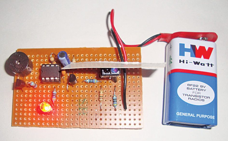
Optoreflective sensor circuit
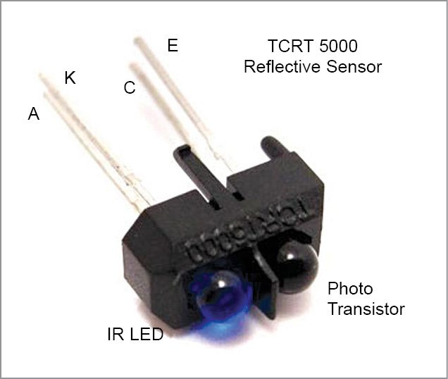
The circuit uses an optoreflective sensor module that has an infrared (IR) LED and a phototransistor in a common package. The IR LED is the transmitter and the phototransistor the receiver. The TCRT5000 in the circuit is a highly-sensitive optoreflective sensor module that has many applications in proximity-detection circuits. It gives two types of outputs (analogue and digital) based on the intensity of the reflecting IR rays falling on the phototransistor.
Analogue output is in terms of DC voltage. That means, when the phototransistor is not receiving the reflected IR rays, output is low, and when the phototransistor gets reflected IR rays, output voltage increases from low to around 3V, based on the intensity of reflected light.

The reflective sensor also has digital output. That means, when the phototransistor is not getting reflected IR rays, output remains in logic 0 (low), and when it gets reflected light, output turns to logic 1 (high). The author’s prototype is shown in Fig. 1.
Circuit diagram of the optoreflective sensor is shown in Fig. 2. Output from the optoreflective sensor (IC1) is used to trigger the monostable circuit built around NE555 timer (IC2.)
Circuit Diagram
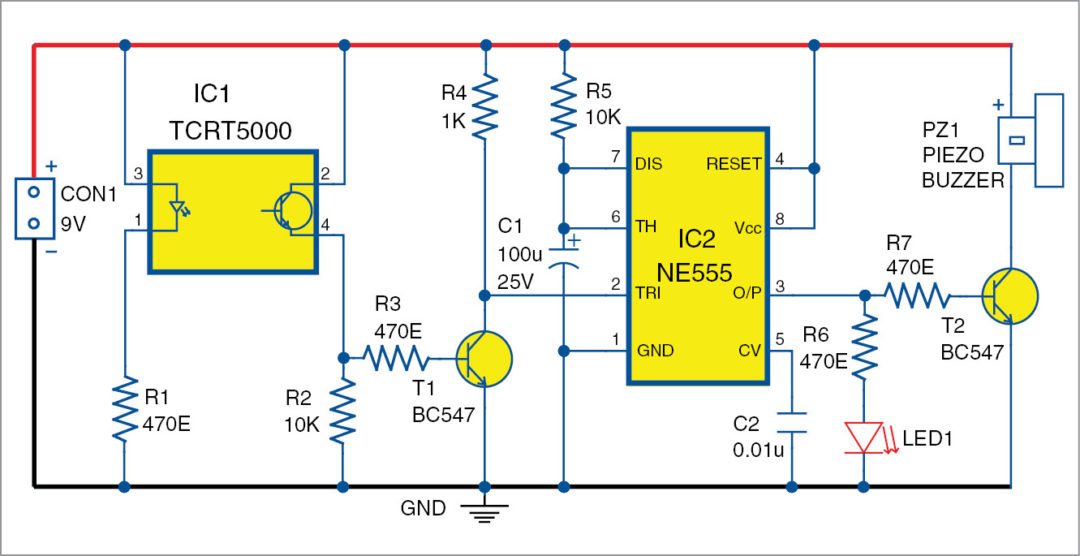
Resistor R1 limits the current through the internal IR LED of the sensor module. In standby mode, IR LED emits continuous IR rays. Phototransistor remains non-conducting since it is not receiving any IR rays.
Timer circuit built around IC2 also remains disabled since its trigger pin 2 is held high through resistor R4. When a reflective object comes in front of IC1 sensor module, the phototransistor inside the module conducts. This makes transistor T1 to conduct, and its collector voltage goes to ground potential, taking trigger pin 2 of IC2 also to ground.
This triggers IC2 and its output pin 3 goes high for around one second, based on the values of resistor R5 and capacitor C1. LED1 indicates activation of the timer and presence of the object in front of the optoreflective sensor. When output of IC2 goes high, transistor T2 conducts and the piezo buzzer sounds.
Construction and testing
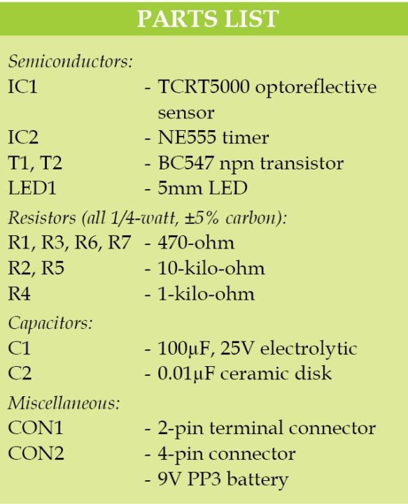
A single-side PCB pattern for the optoreflective sensor is shown in Fig. 3 and its component layout in Fig. 4. Assemble the circuit on the PCB. Use connector CON1 for battery connection and connector CON2 (shown in Fig. 4) for connecting the TCRT5000 sensor module.

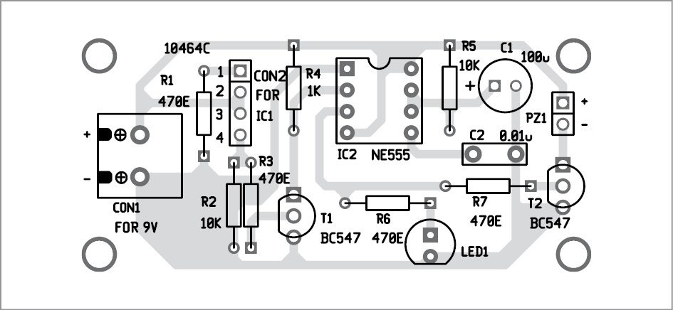
Download PCB and component layout PDFs: click here
Use a 9-volt PP3 battery or a suitable DC power supply. Even though the phototransistor has a filter casing, sunlight triggers the circuit. So test the circuit inside a room where only artificial light is present. Output from the optoreflective sensor can be interfaced with a microcontroller or similar circuits.
Refer Fig. 5 for pin configuration of TCRT5000 sensor before using it in the circuit. Use a 4-wire cable for interconnection between the sensor and the PCB. Connect pins K, C, A and E of the sensor module to pins 1, 2, 3 and 4 of CON2, respectively. Fix the sensor module on the front panel of the cabinet or enclosure.
Feel interested? Check out other electronics projects.
I have designed it on bread board(project board) but its not working,it is ringing buzzer even if nothing is near tcrt5000 and I also tried it in dark room but It didn’t work,please help me with your suggestions
i also designed it on bread board but it was not working,it is ringing buzzer even if nothing is near tcrt5000 ,please help me with your suggestions
it is very much sensitive to sunlight make sure there is no sunlight artificial sunlight is fine
I have done with this and it is now working so perfect,I just changed my both bc547 transistors
Thanks for the feedback!
Which transistors u have changed and why please help me out with that
Hi Saim, it will be nice if you can share transistor used instead of BC547
thanks