
We built the Bus Overload Alert System using Arduino. Now, why and where can we use this detection/counter system?
Child safety is a paramount concern, but, unfortunately, India has one of the highest rates of child fatalities related to transportation incidents.
Shockingly, 19 out of every 100,000 children in India fall victim to such accidents.

A staggering 41% of child deaths in the country can be attributed to these transportation mishaps. It’s a grim reality where, on average, one child becomes injured or loses life every three minutes. Specifically, road accidents claim a child’s well-being every five minutes in India.
Child Safety Crisis in India
The statistics speak volumes, highlighting a pressing issue that demands immediate attention. A substantial number of these accidents result from overloading buses, emphasizing the need for proactive safety measures.
To address this urgent concern, here is a cutting-edge Overload Alert System to track the number of students on board 40-seater buses.
In the event of overloading, this system triggers an alarm, alerting the conductor and the driver to take swift, corrective actions to safeguard the students’ lives.
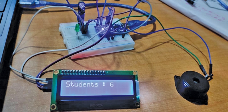
Fig. 1 shows the Overload Alert System’s Prototype.
POC Video Tutorial In English
POC Video Tutorial In Hindi
Bus Overload Alert System – Circuit
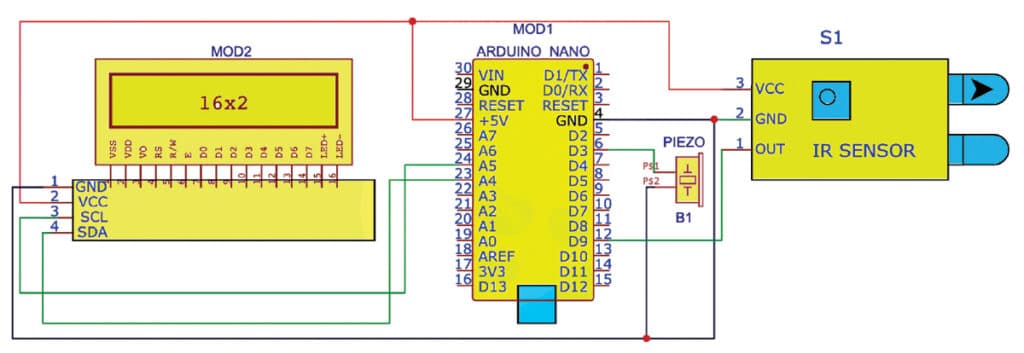
The core of this solution lies in the circuit diagram, as illustrated in Fig. 2. The circuit can be wired on a breadboard, utilizing the power of Arduino Nano.
Its key components include an Arduino Nano (MOD1), an LCD I2C RG1602A (MOD2), an IR sensor module (S1), and a piezo buzzer (B1). The piezo buzzer sounds the alert whenever the student count surpasses 40.
| Parts List | |
| Semiconductors: | |
| MOD1 | – Arduino Nano board |
| MOD2 | – LCD I2C (RG1602A) |
| LED1 | – 5mm LED |
| Miscellaneous: | |
| PZ1 | – Piezo buzzer |
| – Breadboard | |
| – Jumpers wires | |
| – IR sensor module | |
| – 5V USB power adaptor | |
Meanwhile, the LCD I2C visually displays the student count and conveys an overload message when the limit is breached.
Overload Detection System – Code
The programming for this counter is executed within the Arduino IDE. To begin, you must install the LCD library using the library manager.
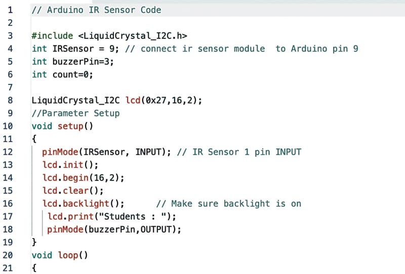
After including the LCD library in the code, you’ll need to define the IR PIN for input (usually set to 9).
Next, specify the buzzer pin (usually pin 3) as an output. Also, set the I2C address for the LCD driver and determine the pixel size (typically 16×2).
Refer to Fig. 3 for a snippet of the code, which sets the pins and I2C address.
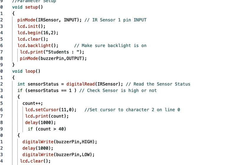
In the code, the IR sensor detects the signal each time a student boards the bus, incrementing the count and displaying it on the LCD.
When the student count reaches the predefined limit, an alert is triggered through the buzzer, indicating an overload situation.
Refer to Fig. 4 for details on the code snippet, outlining the setup and loop function.
Construction and Testing
After uploading the source code STUDENT_counter.ino to the Arduino Nano, assemble the counter on a breadboard or a general-purpose PCB.
Once the circuit is correctly wired, enclose it in suitable housing, including the Arduino Nano board. Mount the LCD on the cabinet’s front side for easy visibility. Power the circuit with a 5V supply from a laptop or desktop via a USB cable.
Monitor the student count on the LCD, which promptly activates an alarm when the count exceeds 40.
Also Check: Interesting Arduino Projects
This alert promptly notifies the conductor and the driver, prompting them to take necessary actions. The circuit was built on a breadboard using jump wires and has undergone extensive testing, exhibiting reliable performance across various scenarios.
Navpreet Singh Tung is in-charge of the Artificial Intelligence and Robotics Lab at Sandeepani Gurukul in Pathankot, Punjab, India