
In some places, especially in developing countries like ours, sudden fluctuations in the mains voltage are quite common.
This sometimes causes a serious damage of electrical appliances like television sets, air conditioners, and refrigerators, which are not designed to tolerate lower or higher voltages beyond a small limit.
So it is important to use overvoltage and undervoltage protection for electrical and electronic appliances. This circuit incorporates a low-voltage and high-voltage tripping mechanism to protect the appliances from any damage due to voltage fluctuation.

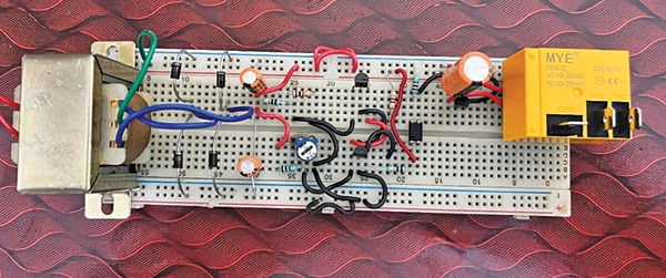
The author’s prototype on the breadboard and the circuit diagram are as shown in the figure.
POC Video Tutorial In English:
POC Video Tutorial In Hindi:
Also, read overcurrent relay for motor protection using arduino.

Overvoltage Protection Circuit Diagram
The circuit’s dual power supply using transformer X1 and diodes D1 through D4 isolates the supply between relay RL1 and control circuitry with the help of optocoupler IC PC817. It helps to eliminate the voltage-dropping problem when the relay energizes.
The capacitors C1, C2, and C3 are used to smoothen the rectified pulsating DC from the diodes.
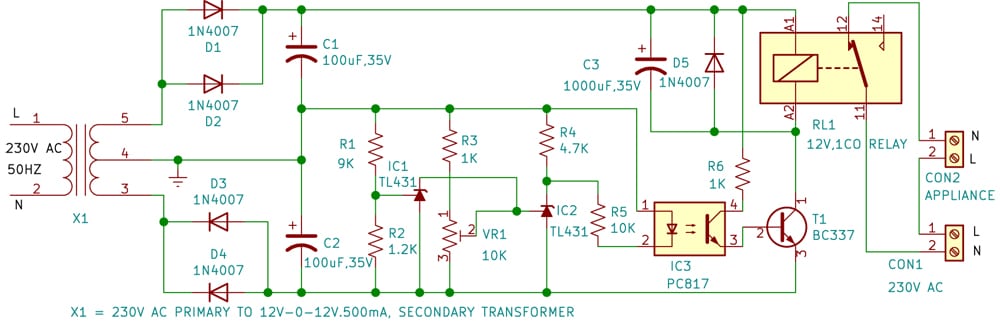
The ICs IC1 and IC2 (TL431) are adjustable shunt regulators. The R1-R2 resistor voltage divider network is used to set the upper cut-off voltage and preset VR1 is used to set the lower cut-off voltage.
Diode D5 works as a freewheeling diode and transistor T1 is used to drive the relay. Resistor R6 biases the internal transistor of the optocoupler and resistor R4 is used to bias the internal transistor of IC2.
| Parts List | |
| Semiconductors: | |
| IC1, IC2 | -TL431 shunt regulator |
| IC3 | -PC817 optocoupler |
| D1-D5 | -1N4007 rectifier diode |
| T1 | -BC337 NPN transistor |
| Resistors (all 1/4-watt, ±5% carbon), unless stated otherwise: | |
| R1 | -9-kilo-ohm |
| R2 | -1.2-kilo-ohm |
| R3 | -1-kilo-ohm |
| R4 | -4.7-kilo-ohm, 0.5W |
| R5 | -10-kilo-ohm |
| R6 | -1-kilo-ohm |
| VR1 | -10-kilo-ohm preset |
| Capacitors: | |
| C1, C2 | -100µF, 35V electrolytic |
| C3 | -1000µF, 35V electrolytic |
| Miscellaneous: | |
| X1 | -230V AC primary to 12V-0-12V, 500mA secondary |
| RL1 | -12V single changeover relay |
| CON1, CON2 | -2-pin terminal connector |
| -3-pin terminal connector | |
Also check: Overcurrent Fault Detector.
The secondary voltage of transformer X1 proportionally changes as the primary (AC mains) voltage changes. This change reflects at the external reference pins (pin 1) of IC1 and IC2. The R1-R2 resistor network sets the pin 1 voltage below the internal reference voltage of IC1.
IC1 acts as an open circuit that exists between cathode pin 3 and anode pin 2 of optocoupler IC3. Preset VR1 is adjusted to set the pin 1 voltage of IC2 above the internal voltage reference of IC2. In this case, IC2 acts as a short circuit and so the optocoupler keeps conducting.
The optocoupler output biased through R6 is fed into the base of transistor T1, which drives relay RL1 to on state. If the voltage increases and becomes greater than the internal reference voltage at pin 1 of IC1, the optocoupler starts conducting between pin 3 and pin 2 and acts as a short circuit.
This sets IC2’s reference pin 1 below the internal reference voltage and forces IC2 to an open-circuit state, so the optocoupler and relay turn off and switch off the load. The same happens when the voltage decreases at pin 1 of IC2 due to a fall in AC mains voltage.
Construction and Calibration
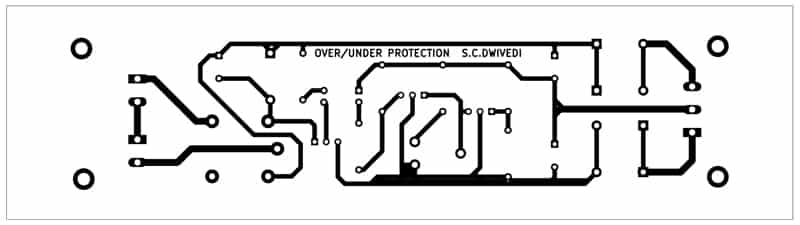
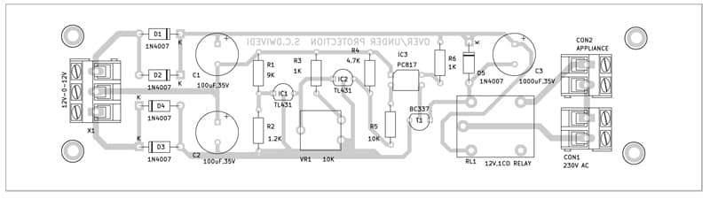
An actual-size, single-side PCB layout for the circuit is shown in Fig. 3 and its component layout is shown in the above figure After assembling the circuit on PCB, enclose it in a suitable box. Fix VR1 outside the box after proper calibration (if using a pot in place of preset). Fit the transformer inside the box.
For the calibration, you may use a variac (variable transformer) for setting the over-voltage and under-voltage limits. The over-voltage limit has been set around 270V with the help of resistors R1 and R2, which you can change (if required) by changing the values of these two resistors.
For the under-voltage limit, set the variac to around 180V and set the preset in such a way that the relay energizes at this voltage. This completes the calibration.
After calibration, enclose the box and connect the 230V AC mains voltage to the primary of transformer X1. Connect the AC mains and the appliance to be protected across connectors CON1 and CON2, respectively. Now your circuit is ready to use.
Download PCB and Component Layout PDFs: click here
Shamail Ahmad is B.E. (ECE) and has 12 years of experience in Electronics R&D. He is working as CTO at Harlen Automation Private Limited, New Delhi