


 A password locker usually has an electromagnetic lock that opens only when the correct password is entered. The circuit presented here for such a locker is a simple, low-cost, hi-security six-digit password-operated system. ATtiny2313 microcontroller (MCU) used in the circuit is easily available and programmable using any AVR programmer.
The circuit diagram of the password locker is shown in Fig. 1. It is built around ATtiny2313(IC1), 2N2222 transistor (T1), 16×1 LCD (LCD1), 5V single-changeover relay and a few other components.
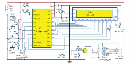
The twenty-pin ATtiny2313 MCU is the heart of the project. First, a six-digit password has to be saved in the EEPROM of the MCU. The lock opens when this password is entered. The saved password is available even after disconnecting the power supply. But the six-digit password can be erased, and a new password generated, if required.

Only three buttons are used here for entering or saving the password. A blinker LED (LED1) is used as the status indicator of the MCU process.
 One out of the six digits of the password is displayed at a time and allowed to be edited. Remaining five digits appear as asterisks (*) in the LCD display. Cursor of LCD1 blinks when password digits are entered.
Up button is used to change the digit from 0 to 9. Similarly, Right button is used to move the cursor right for editing. Once the password is entered, press Enter to start processing the entered password.
Jumper J1 is provided to erase the existing password. Close J1 and then power on the circuit; the existing password, if any, will be erased and the new password may now be entered. Once a new password is successfully saved to EEPROM, disconnect or open J1, which should not be accessible to any other user.
In case of a new chip, while using it for the first time, the display will show ‘New PWD:’ message and wait for the six-digit password to be entered. The password (except 000000, which is invalid) will be saved to the EEPROM and displayed on the LCD. Any password from 000001 to 999999 may be used.
Now, the display will show ‘Open PWD:’ message and wait for the six-digit password. If the password matches with the saved password, the relay will energise for ten seconds and ‘Lock Opened’ message will appear on LCD1. After ten seconds, relay RL1 will de-energise and the display will wait for the password again.
In case, the password does not match with the saved password, the display will show ‘Invalid’ and wait for the correct password.
A 5V DC power supply (300mA or above) is required to operate the circuit.
The firmware code (PasswordLock.c) for ATtiny2313 MCU is written in C language. Hex code can be generated using any AVR C compiler such as Programmers Notepad (WinAVR).
Construction and testing
A PCB layout of the password locker is shown in Fig. 2 and its components layout in Fig. 3. After assembling the circuit on the PCB or veroboard, program/burn ATtiny2313 with passwordlock.hex file using AVR programmer.

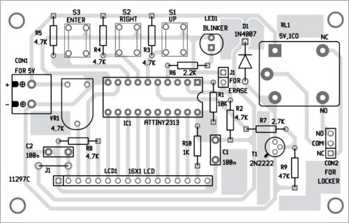
Download PCB and component layout PDFs: click here
Connect 5V DC power supply across connector CON1. For the first time, you will have to set a password as explained above. The blinker LED1 blinks while waiting for password input. If the password is correct, RL1 will energise and the lock connected across the relay contacts will open. The LED1 will now glow continuously, indicating the circuit is ready to use.
Fayaz Hassan is a manager at Visakhapatnam Steel Plant, Visakhapatnam, Andhra Pradesh. His interest includes MCU projects, mechatronics and robotics


hI Master, Good day!! The firmware code (PasswordLock.c) for ATtiny2313 MCU is written in C language. Hex code can be generated using any AVR C compiler such as Programmers Notepad (WinAVR)?? May I know where is the Firmware code??
How to hear to u soon. Take care
Cheers
Jacky
Please download the code from here: https://efy.efymag.com/admin/issuepdf/Make%20Your%20Own%20Password%20Locker.zip