


 Here is a simple yet very useful phone broadcaster circuit which can be used to eavesdrop on a telephone conversation. The circuit can also be used as a wireless telephone amplifier.
One important feature of this circuit is that the circuit derives its power directly from the active telephone lines, and thus avoids use of any external battery or other power supplies. This not only saves a lot of space but also money. It consumes very low current from telephone lines without disturbing its performance. The circuit is very tiny and can be built using a single-IC type veroboard that can be easily fitted inside a telephone connection box of 3.75 cm x 5 cm.
Phone broadcaster circuit
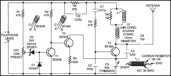
The circuit consists of two sections, namely, automatic switching section and FM transmitter section. Automatic switching section comprises resistors R1 to R3, preset VR1, transistors T1 and T2, zener D2, and diode D1. Resistor R1, along with preset VR1, works as a voltage divider. When voltage across the telephone lines is 48V DC, the voltage available at wiper of preset VR1 ranges from 0 to 32V (adjustable). The switching voltage of the circuit depends on zener breakdown voltage (here 24V) and switching voltage of the transistor T1 (0.7V). Thus, if we adjust preset VR1 to get over 24.7 volts, it will cause the zener to breakdown and transistor T1 to conduct.

As a result collector of transistor T1 will get pulled towards negative supply, to cut off transistor T2. At this stage, if you lift the handset of the telephone, the line voltage drops to about 11V and transistor T1 is cut off. As a result, transistor T2 gets forward biased through resistor R2, to provide a DC path for transistor T3 used in the following FM transmitter section.
The low-power FM transmitter section comprises oscillator transistor T3, coil L1, and a few other components. Transistor T3 works as a common-emitter RF oscillator, with transistor T2 serving as an electronic ‘on’/‘off’ switch. The audio signal available across the telephone lines automatically modulates oscillator frequency via transistor T2 along with itsseries biasing resistor R3. The modulated RF signal is fed to the antenna. The telephone conversation can be heard on an FM receiver remotely when it is tuned to FM transmitter frequency.
Lab Note
During testing of the circuit it was observed that the telephone used was giving an engaged tone when dialed by any subscriber. Addition of resistor R5 and capacitor C6 was found necessary for rectification of the fault.
