


This portable solar-powered lantern with auto bedlight for everyday use can be made with easily available components.
The circuit diagram of the portable solar lantern cum bedlight is shown in Fig. 1. It is built around a 5.5V, 60mA solar panel, LDR1, transistor BC547 (T1), 1-watt white LED (LED2), two 1N4007 rectifier diodes (D1, D2), and a few other components.
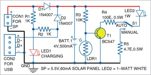
The solar panel powers the circuit. When the panel is under the sun, it charges the 4V lead-acid battery (BATT.1) via diode D1. Within eight hours, the battery gets almost fully charged. There is an option to charge the battery via a 5V USB charger during rainy season or when sunlight is not present. Charging is indicated by LED1.

You can switch on the lantern using switch S1, which has two positions: auto and manual. During day time, if S1 is kept in auto mode, the lantern’s white LED2 will not glow.
During night time, LDR1 offers high resistance, which allows transistor T1 (BC547) to conduct through resistor R3. This makes LED2 glow, so it can be used as a bed-light or night lamp.
The LDR automatically takes care of the load during day time as well as night time in auto mode. When S1 is in manual mode, you need to switch off LED2 either by removing the battery, or solar panel, or the USB charger.
Construction and testing
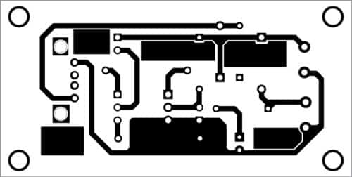
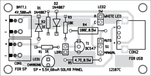
An actual-size PCB layout of the portable solar lantern cum bedlight is shown in Fig. 2 and its components layout in Fig. 3. After assembling the circuit on PCB, connect a 4V battery to the circuit. For charging the battery, connect the 5.5V solar panel across CON1 or a 5V USB charger across CON2.
Download PCB and component layout PDFs: click here
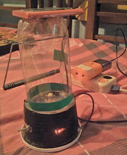
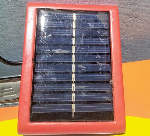
The author’s prototype is shown in Fig. 4, and 5.5V solar panel used in the project is shown in Fig. 5.
Check the 10 best solar electronics projects.
P.V. Vinod Kumar is an electronics and communication engineer, electronics hobbyist and circuit designer

