


This project addresses the automatic wiper and car security system for a car. Apart from that, it takes care of the security in terms of Smartphone App based monitoring and control of the car door.
The innovation is in terms of use of Arduino Nano for Automatic activation of the wiper when rain falls as well as the speed control of the same under heavy or light rain conditions. Also the PCB is a double sided compact sized one implemented with Eagle software.
Here in this project, the wiper system is a single motor based wiper which wipes the Car Windshield at once. It also changes its speed automatically depending on the intensity of rain falling.

The cost of this Project is ₹ 1790 (Around 23 $).
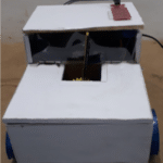
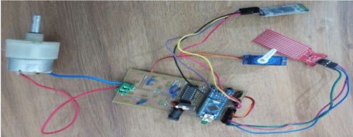
Description of Prototype
The Rain Sensor is placed on the top of the car.
Car Surface Dimension—Width -20cm & Length-12cm.
Car Door Dimension— Width-5cm & Height-5cm.
Car Bonnet Dimension—Width-10cm & Length-12cm & Height-6cm.
Car Dimension— Width-10cm &Length-12cm & Height-10cm.
The Internal Structure falls into 3 categories and are as follows:-
1) Circuit Designing & Printing PCB
2) Android Application Designing
3) Coding in the Software
List of Components used for automatic wiper and car security system:
| Serial No. | Components | Quantity | Technical Specifications |
| 1 | Arduino Nano v3.0 | 1 | Any Arduino Family Microcontroller is applicable |
| 2 | Servo Motor | 1 | SG-90 Servo Motor |
| 3 | Water/Rain Sensor | 1 | Senses the water and act as a Conducting Switch |
| 4 | HC-05 Bluetooth Module | 1 | Range upto 10m with Frequency of 2.4 GHz and easily connected to Smartphone devices |
| 5 | L293D | 1 | H-Bridge Motor Driver to Drive Motor |
| 6 | IC 7805 | 1 | Regulate the Input Voltage to 5V as its Output |
| 7 | Motor | 1 | 12V DC Geared Motor |
| 8 | 10uf Capacitor | 2 | 10ufarad 63V capacity |
| 9 | LED | 3 | |
| 10 | Screw Clamp | 1 | Wago Screw Clamp 2 port Connector |
| 11 | 12V DC Jack | 1 | DC Jack for connecting the 12V Adapter Pin- |
| 12 | Jumper Wires | – | |
| 13 | Batteries/ Adapter | 1 | 12V Adapter or 12V Battery Pack is used |
Circuit Diagram & Connections
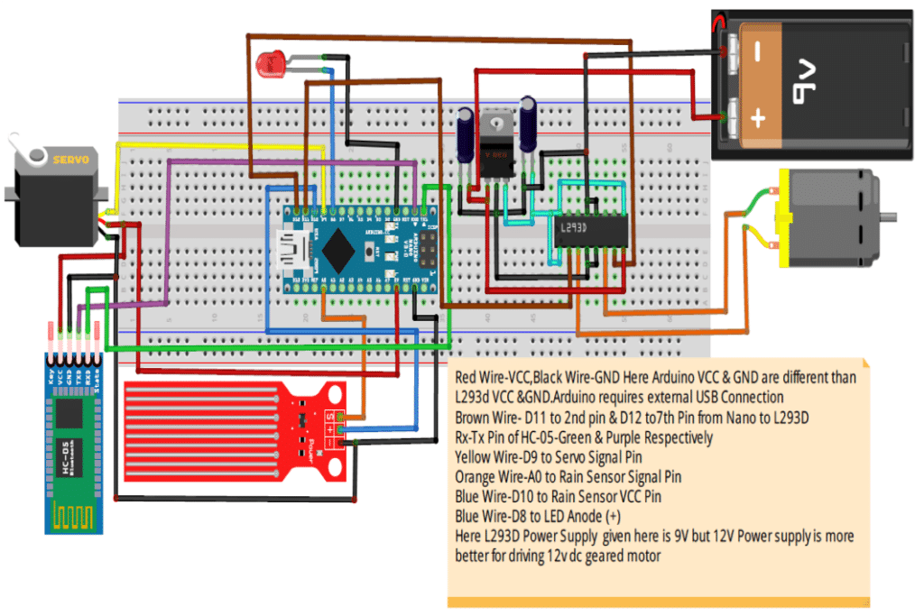
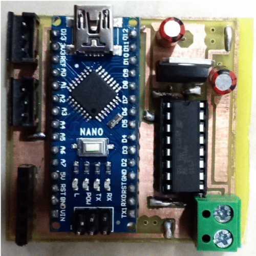
The image shows the whole Circuit Diagram of the Project. The Important Element of this project is the Arduino Nano v3.0 Microcontroller. As this project is compatible with any Arduino Family Microcontroller, but due to small size and compact body we preferred Arduino Nano. The Arduino Nano is connected with the other components which also plays an important role in this project. These components are the Rain Sensor, HC-05 Bluetooth Module, SG-90 Servo Motor & L293D H-Bridge Motor Driver IC.
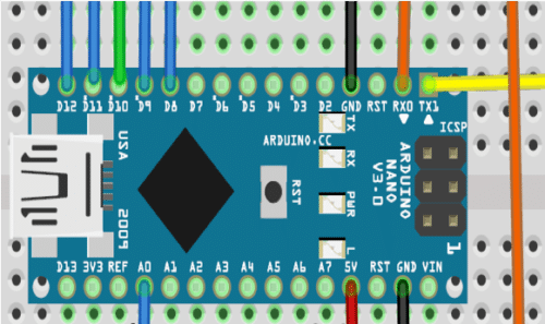
Arduino Nano with the interfaced components.
Arduino Nano dimension is 18mm x 45mm
Final PCB dimension is 50mm x 50mm
Comparison of Arduino Nano Versus Arduino Uno Microcontroller
| Arduino Nano | Arduino Uno |
| 22 digital input/output pins of which 6 can be used as PWM outputs; 8 analog Inputs. | 14 digital input/output pins of which 6 can be used as PWM outputs; 6 analog inputs. |
| Arduino Nano is made up with either using ATmega328 / ATmega168 Microcontroller. | Arduino Uno is made up using ATmega328P Microcontroller. |
| ATmega328 has 32 KB of Program Flash Memory and 2KB of SRAM ATmega168 has 16KB of Program Flash Memory and 1KB of SRAM. |
ATmega328P has 32KB of Program Flash Memory of which 0.5 KB used by boot loader and 2KB of SRAM. |
| Nano can be powered via the Mini-B USB connection. It lacks only a DC power jack, and works with a Mini-B USB cable instead of a standard one. | While the Arduino Uno is powered using USB 2.0 B port and a DC Power Jack. |
| Arduino Nano Board uses using Surface Mounting Device (SMD), a component due to which the Board Size is smaller and the PCB is of 2 layers (i. e Top & Bottom Layer PCB Combination). | Arduino Uno board uses combination of Surface Mounting Device (SMD) and Through Hole Components (THT). In Arduino Boards the microcontroller is available in both forms. |
| Arduino Nano Board is 18mm X 45mm. | Arduino Uno Board is 68.6mm X 53.4mm. |
| Its small size would be a plus point for this microcontroller to be used in developing any commercial product | Due to its bulk size this board is mostly used by the Arduino Beginners for developing the skills on Arduino. |
Following are the details of the Interfacing of the Arduino Nano:
Arduino Nano Interfacing with LED:
LED (+) Anode Pin -> Arduino Nano D8 Pin
LED (-) Cathode Pin -> Arduino Nano GND Pin
Arduino Nano Interfacing with Rain Sensor:
Rain Sensor S Pin -> Arduino Nano A0 Pin
Rain Sensor (- ) GND Pin -> Arduino Nano GND Pin
Rain Sensor (+) VCC Pin -> Arduino Nano D10 Pin
Arduino Nano Interfacing with Servo Motor(SG-90):
Servo Motor (SG-90) S Orange Color Pin -> Arduino Nano D9 Pin
Servo Motor (SG-90) (- ) Brown Color GND Pin -> Arduino Nano GND Pin
Servo Motor (SG-90) (+) VCC Red Color Pin -> Arduino Nano 5V Pin
Arduino Nano Interfacing with HC-05 Bluetooth Module:
HC-05 Bluetooth Module RX Pin -> Arduino Nano TX1 Pin
HC-05 Bluetooth Module TX Pin -> Arduino Nano Rx0 Pin
HC-05 Bluetooth Module (- ) GND Pin -> Arduino Nano GND Pin
HC-05 Bluetooth Module (+) VCC Pin -> Arduino Nano 5V Pin
Arduino Nano Interfacing with l293D H-Bridge Motor Driver IC:-
l293D 2nd Pin -> Arduino Nano D11 Pin
l293D 7th Pin -> Arduino Nano D11 Pin
Printing PCB
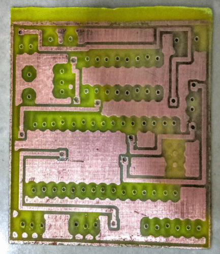
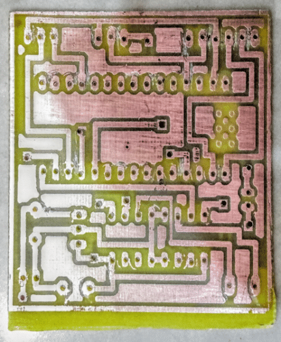
The above image shows the Top Layer and Bottom Layer of PCB respectively.
Both the layers have to be connected with each other through Vias which are present in both the layers.
To print such type of PCBs we require a double-sided copper plate.
Such circuits are compact and small so that it requires less space.
In case of difficulty, while printing this PCB, we have also developed the PCB with Bottom Layer only.
Android Application
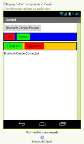
The Above Image shows the Android Application Designed at MitAppInventor.com. It is highly flexible in developing App for the Beginners. The user can also customize the components in the APP by changing its properties which are shown on the right side of the image.
We have used it for Car Security by means of locking and unlocking of car door via Smartphone. The App is connected to the Car System via Bluetooth which is secured Communication Protocol as compared to Wi-Fi Communication.
Description of the Buttons present in the App
Bluetooth Device Present——– Shows the Nearby Bluetooth Receiver Devices
UNLOCK DOOR ——— Unlocks the Car Door
LOCK DOOR ———– Locks the Car Door
Engine ON ——–Turns On the Car System
Engine OFF ——–Turns off the Car System
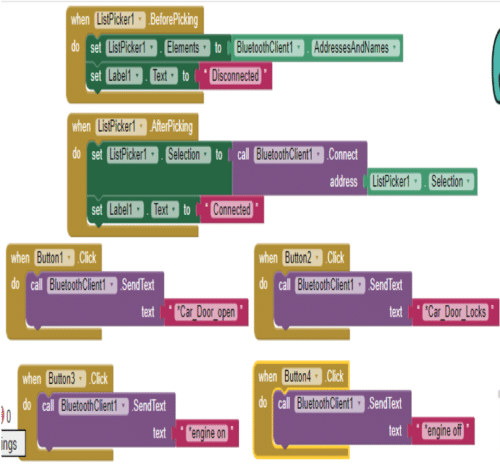
Now here the above image describes the Design Blocks of the Application that is formed in Designer Section.
The first two Puzzle Blocks defines the function of Bluetooth Device Present Button.
These Blocks would display the nearby Bluetooth Client Available on the App Screen and the App would show the disconnected symbol written on the App until it gets paired with the Bluetooth Client.
The Second Puzzle Block would display connected Symbol on the App screen if and only if the App gets connected to the Bluetooth Client.
Another four Puzzle Block would define the Function of the Buttons. At each of these 4 Blocks at last there is text written in the pink puzzle block. This text describes the data that were written in the code, as these texts would be used to make Microcontroller Serial Read the loops and function it accordingly. For example,
On pressing Unlock Button,
*Car_Door_Open command is sent to the microcontroller via HC-05 Bluetooth Module
Microcontroller Serially Reads this command than it activates the Unlock_Car_Door loop
Car Door will open.
The 1st Button block functions as the Car Door opener
2nd Button would function as the Car Door Lock.
The 3rd & 4th Button would turn On & Off the Engine Respectively.
Software Code Algorithm
#define Rain_sensor A0 // Analog pin A0 of Arduino Nano
int Motorinp-1=11;
int Motorinp-2=12;
int Engine=8;
int Sensorinput=10;
int Servo Input=9;
int inp=0; // Value which connects the Unlock Door Loop with Engine_On_Off loop//
int rs=0; // Value which connects the Rain Sensor loop with Engine_Off loop//
String data; //Read Serial Data//
int pos=0; // define Servo Position//
int val; // Read Analog Value//
————————————————————————————————————————–
#include
#include
————————————————————————————————————————–
void setup()
{
(Motorinp-1, OUTPUT);
(Motorinp-2, OUTPUT);
(Sensorinput, OUTPUT);
(Engine, OUTPUT); (
Rain_sensor, INPUT); // Defining the pinModes//
Serial.begin(9600); // Baud Rate//
mySerial.begin(9600); // Serial Read takes place at 9600 baud rate per second//
}
————————————————————————————————————————–
void loop()
{ while (mySerial.available())
{ delay(10 );
char c = mySerial.read();
if (c == ‘#’)
{ break; }
data += c; }
————————————————————————————————————————–
if (data.length() > 0)
{
If (data == “a”) // If the Serial Read value is a than Unlock _Car _Door loop gets active. //
{ Unlock_Car_Door(); // Car Door gets unlock//
inp=1; // This value will activate the Engine_On & Engine_Off loop// }
else if(data == “b”) //If the Serial Read value is b than Lock_Car _Door loop active. //
{ Lock_Car_Door(); // Car Door gets lock//
inp=0;
Engine_Off(); // Car system gets deactivate// }
else if(data == “c” && inp == 1 ) //Unlock_Car_Door loop activates Engine_On Loop. //
{ Engine_On(); // Car system gets deactivate// }
else if(data == “d” && inp == 1 ) //Unlock_Car_Door loop activates Engine_Off Loop. //
{ Engine_Off(); // Car system gets deactivate// } }
if(inp==1 && rs==1) // Unlock_Car_Door & Engine_ON loop activates Engine_Off ///
{ RainSensor(); }
data=””; }
————————————————————————————————————————–
void Unlock_Car_Door()
{ myservo.write(pos); // Door will move in Clockwise Direction//
delay(z); // On basis of requirement of how fast door should work// }
void Lock_Car_Door()
{ myservo.write(pos); //Door will move in Anticlockwise Direction//
delay(z); // On basis of requirement of how fast door should work// }
void Engine_On()
{ Engine pin gets HIGH // digital output//
Sensorinput pin gets HIGH // digital inputs//
RainSensor(); // RainSensor Loop//
rs=1; // Value which connects the Rain Sensor loop with Engine_On loop// }
void Engine_Off() // Engine Off loop//
{ Engine pin gets LOW // digital output//
rs=0; //// Value which connects the Rain Sensor loop with Engine_Off loop//
Sensorinput getsLOW); //digital input//
Motorinp-1 pin gets LOW // digital output//
Motorinp-2 pin gets LOW // digital output// }
————————————————————————————————————————–
void RainSensor() // Rain Sensor Loop//
{
val= analogRead(Rain_sensor); // Rain Sensor Values//
if(val>x1 && val<x2) //Rain Sensor Values such that x2>x1//
{ Motorinp -1 pin gets HIGH // digital output//
Motorinp-2 pin gets LOW // digital output//
delay(y1);
Motorinp-2 pin gets HIGH // digital output//
Motorinp-1 pin gets LOW // digital output//
delay(y1); }
else if(val>x2 && val<x3) //Rain Sensor Values such that x3>x2//
{ Motorinp -1 pin gets HIGH // digital output//
Motorinp-2 pin gets LOW // digital output//
delay(y2); //
Motorinp-2 pin gets HIGH // digital output//
Motorinp-1 pin gets LOW // digital output//
delay(y2); }
else if(val>x3 && valx3//
{ Motorinp -1 pin gets HIGH // digital output//
Motorinp-2 pin gets LOW // digital output//
delay(y3);
Motorinp-2 pin gets HIGH // digital output//
Motorinp-1 pin gets LOW // digital output//
delay(y3); }
else if(val<x0) //Rain Sensor Values such that x0< x1
{ Motorinp-1 gets LOW // digital output//
Motorinp-2 gets LOW // digital output// } }
————————————————————————————————————————-
Check the tested Arduino projects.
Actually, I’m a electronics student .I’m interested in embedded domain. So I’m thinking it will be useful as well as helpful
sir i want to do your project but it gives errors, sir please give the original code
Can you please share your code and progress on [email protected]?