


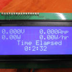
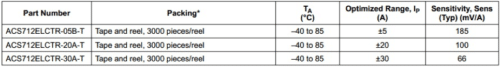
 This project describes how to make a low-cost DC power meter that can be used for displaying Voltage, current, power and the running time of operation. This is useful and can be used as the display for your bench power supply too. This can be used in the display section of a 0-55 v battery charger, so the time elapsed gives you the actual time of charging the battery. The measurable voltage range of this circuit is 0-55V DC and current depends on the type of sensor used. Here in this project, I have used ACS 712 – 20A Hall Effect sensor and it has a current measuring capacity of up to 20 Amperes. There are three types of ACS 712, they are 30 A, 20A, and 5 A. All these sensors has different sensitivity value and this sensitivity should include in the formula if you use a different sensor. Please refer to the datasheet of the sensor to get more information.
Parts Required
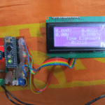
1. Arduino Nano
2. 20 X 4 LCD display
3. ACS712 ELCTR20A-T
4. 100k resistance
5. 10k resistance
6. 10k Variable resistance
7. General purpose circuit board
8. 2 pin TBC connector /Dc jack for input supply
9. 2 pin polarized header wire: relimate connector

Circuit and description
Voltage measurement
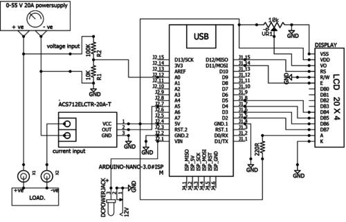
The Arduino board contains a 6 channel (8 channel on the mini and Nano, 16 on the mega), 10 bit analog to digital converter. This analog channel map voltage between 0 and 5 into integer value 0 to 1024. And it is dangerous to give more than 5 voltage to Arduino port so in this circuit a voltage divider is used for map 0-55 voltage to the 0-5 voltage. Voltage divider has constructed with 2 resistance network 100k and 10k. Power factor = input voltage/ output voltage
Power factor = 55/5=11
The value of voltage can be measured by the formula voltage = {[ADC value of voltage] x [5/1024] x [R2/R1+R2] x [power factor]}
Current Measurement
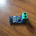
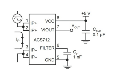
For measuring current, a current sensor ACS 712 has interfaced with Arduino. ACS 712 is a Hall Effect current sensor. It has a very high response time and the output error is about 1.5 per cent. But it can be tackled with some intelligent programming and multiplying measured value with a standard error of sensor. When the DC current flowing through the input of sensor it will give proportional DC voltage at the output of sensor. Proportional sensitivity of ACS 712 sensor is
Note:
1. Make sure that you never connect IP+ and IP- in parallel to the source of supply that will damage your device.
2. This device is a Hall Effect transducer. It should not be used near significant magnetic fields.
3. If you are getting zero current on display but everything is correct, then check the series input and output connection of ACS712 sensor and check the voltage out of module it should be Vcc/2.
4. For most accurate result run the Arduino from an external power supply instead of USB.
5. This circuit designed for measuring DC values so do not connect it to AC.
Pin number 7 is the output pin of ACS 712 current sensor. ACS712 ELCTR20A-T sensor can measure current in the range of +-20 and output sensitivity is 100mV /A. It means the output voltage which will appear at the output pin of the current sensor is 100mV for every ampere pass through the Hall Effect sensor. Similarly for other sensors with different sensitivity. Tothe calculate current from output voltage of ACS712, do the calculations according to the following points.
1. When no current flows through the sensor, the output voltage will be Vcc / 2, where Vcc is power supply voltage given to given to ACS712 current sensor.
2. If Vcc is 5v then output voltage of current sensor will be equal to 2.5v, when there is no current passing through the sensor.
3. 2.5v is offset voltage of sensor, measured voltage should be subtracted from offset voltage.
4. The output voltage decreased when current passing through it.
So we can calculate dc current by using following formula
Current = {2.5 – [Arduino measured ADC value of voltage] x [5/1024] x Sensitivity}
DC current by using the following Commands:
AcsADCValue = analogRead(A5); // analogRead(A5)Reads the value from the analog pin A5.
AcsValueF= (AcsADC*0.0048828125); // AcsValueF is the Voltage reads by ACS 712 sensor //5/1024=0.0048828125
float Current = AcsValueF/.1; // sensor ACS 712 20A has sensitivity of 100mV ,
//Sensitivity of 30A is 66mV and sensitivity of 5A is 185 mV
//use this value in the code with respect of your sensor current capacity.
//Current = (AcsOffset – (Arduino measured analog reading)) / Sensitivity)
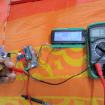
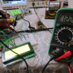
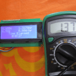
Once the circuit assembled and tested, check the value of voltage with a multimeter and minutely adjust the values in formula so that it can reduce its error.
AvgAcsADC should be 512 or 511 ie, Arduino ADC reads 5 volt at A5 port as 1024. At zero current, 2.5 volt will present in A5 port. That means ADC of Arduino reads 2.5v as 512 or 511 (5/2=2.5 and 1024/2=512). If it is 510 or below result will be -ve value in current reading. So for a correction in this make the next de-activated line (AvgAcsADC+=1) active with the numeric number 1 or 2 according to your sensor input.
Download Source Folder

A small correction in the above Project description :-
*******************************************************************************
DC current by using following Commands:-
AcsADCValue = analogRead(A5); // analogRead(A5)Reads the value from the analog pin A5.
AcsValueF= (AcsADCValue*0.0048828125); // AcsValueF is the Voltage reads by ACS 712 sensor //5/1024=0.0048828125
AcsValueF – =2.5; // When zero current flows through the sensor it shows a voltage of // VCC/2 ie 5/2= 2.5v this known as offset voltage.
//For getting value of current, current = offset voltage – voltage measured by ACS sensor / sensitivity
float Current = AcsValueF/.1; // sensor ACS 712 20A has sensitivity of 100mV , //Sensitivity of 30A is 66mV and sensitivity of 5A is 185 mV
//use this value in the code with respect of your sensor current capacity.
//Current = (AcsOffset – (Arduino measured analog reading)) / Sensitivity)
Thank you Gireesh, we will reverify the article.
I was searching for the current and voltage calculation formula for Arduino and so many misleading videos projects found at net . This seems good and thank you.
This circuit will work up to 55v but accuracy will decrease after 30V in voltage measurement. how ever when i tested at 30v their was a difference of .3 v from actual reading. how ever those who are trying this please give their inputs too. i tried my level best to explain each line of code in the program itself.
hello gireesh kumar sir i need a circuit for -ve 48volts dc can you help me??
I am sorry for my late reply. For this i request you to visit a youtube page named “Long Technical” he is anexpert in making powersupply SMPS . Many of his videos he described about how to wind a transformer in an smps too. He will be more suitable than me in that subjuct. Once you visit that youtube page youwill get plenty of circuits with pcb layouts.
well great project .. but i think this acs712 can cause false readings near magnetic field.. Great Trap be aware. i think you need to consider Shunt based i mean 0.1 ohm or less .. use Amplifier configration (Low Offset to amplify) it will be great Project… i am not good in programming but can deeply design any analogue circuits…
Dear Avinash, I also got same information from internet about acs 712 while I started to doing same but it was my experiment and from my findings understand it’s not that much faulty as described in internet. I have updated the whole set up this and made a work bench power supply having power meter display. I have used 25- 0-:25 v transformer having 5A current and don’t have any error as per my findings. Still I’m using it.