


 Gas detector systems are mainly used for sensing the presence of gas leaks and then taking an action, such as automatically shutting down the source of gas or sounding an alarm to inform the people in the area about the gas leak.
Presented here is a microcontroller (MCU)-based wireless liquefied petroleum gas (LPG) detection and monitoring system. It is multi-node and, therefore suitable for use in caravan sites, holiday homes, students’ halls of residence, old peoples’ homes, university campuses and other places where groups of people live, and a large number of detectors may be required.
Semiconductor gas sensors
The MQ series of gas sensors are highly popular and are used in most domestic and industrial gas detection applications. These are semiconductor sensors with SnO2 as the sensitive material. The sensors have low conductance in clean air, but their conductivity rises when subjected to the gas being sensed. Change in conductivity is converted to an analogue output signal through a simple circuit. Detection ranges of these sensors depend on the type of sensors used.

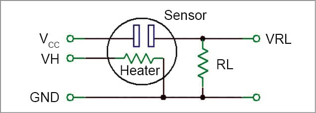
As shown in Fig. 1, MQ series of gas sensors require two voltage inputs: heater voltage (VH) and circuit voltage (VCC). Heater voltage is specified as 5V and can be AC or DC. Circuit voltage is 5V DC and should be connected as shown in the connection diagram. In most applications, the same 5V voltage is used to power both the heater and the internal sensor circuitry.
The manufacturer provides sensitivity curves showing the gas concentration against the ratio of sensor resistance to resistance in clean air.

MQ-6
This sensor is used to detect LPG concentrations in the air, which are mainly composed of propane and butane. SnO2 is the sensitive material of this sensor, and its conductivity changes when exposed to LPG. The sensor can detect gas concentrations in the range of 200ppm to 10,000ppm. As with other sensors, an internal heater is used. The sensor provides an analogue output voltage proportional to ambient gas concentration.
Design of wireless gas detection and monitoring systems
The block diagram of the designed system is shown in Fig. 2. The system consists of two parts: gas detection stations and gas monitoring station. A gas detection station consists of a semiconductor gas sensor and an MCU that receives signals from the gas sensor and activates a suitable transmitter module. This detection or transmitter station sends a message to the monitoring station along with a unique station ID to alert the user about the gas leakage along with its location.
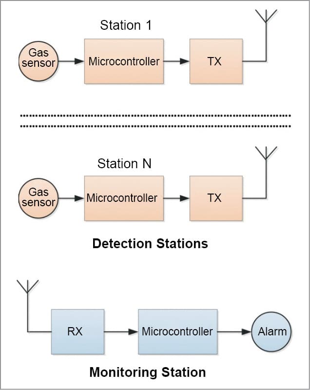
In this design, four switches are used, which makes it possible to have up to 16 detection stations. Their unique IDs range from 0 to 15, selected using switches.
Circuit and working
Both detection and monitoring stations use low-cost 8-bit medium-performance PICF family of MCUs. Hardware details of each station are given below.
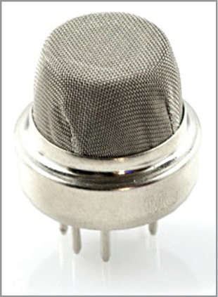
Detection and transmitter stations. MQ-6 semiconductor LPG gas sensor (Fig. 3) is used in the design, since it is highly sensitive, low cost and easy to use. LPG concentrations above 1000ppm are accepted to be toxic and should be avoided. The system has been designed to activate if LPG concentration is above 1000ppm.
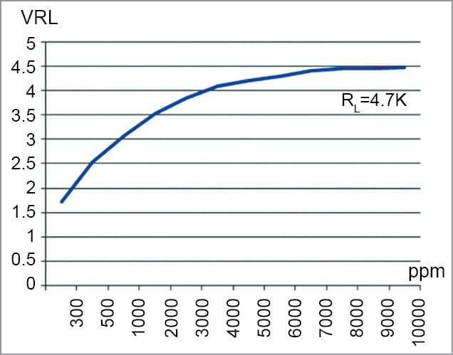
MQ-6 pins are organised in groups of three pins on each side of the sensor, where pins 2 and 5 are heater pins, and pins 1 and 3 and pins 4 and 6 are sensor circuit pins. As shown in Fig. 1, load resistor RL is connected in series with sensor resistance Rs to convert resistance Rs to voltage. Fig. 4 shows the sensor output voltage when a 4.7-kilo-ohm load resistor is used.
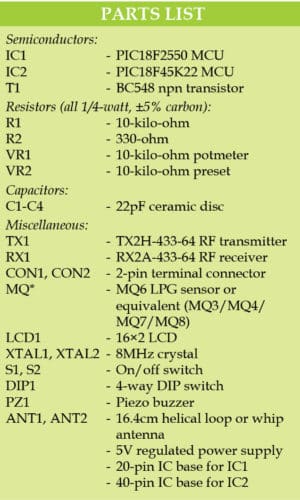
The circuit diagram of the gas detection station is shown in Fig. 5. It is built around an MQ* series LPG gas sensor, PIC18F2550 MCU (IC1), TX2H-433-64-5V 433MHz transmitter module (TX1), 4-way DIP switch (DIP1) and a few other components. MQ* LPG sensor may be MQ-3, MQ-4, MQ-6, MQ-7 or MQ-8.
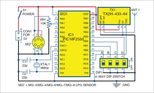
PIC18F2550 is used in the design with an external 8MHz crystal. PLL clock multiplier is used to increase the operating clock frequency from 8MHz to 48MHz. Sensor output is connected to a 10-kilo-ohm variable resistor, which feeds into analogue input channel RA1 of the MCU.
Sensitivity of the device can easily be adjusted via this potentiometer. Whenever a gas leakage is detected, a message is sent to the monitoring station together with the unique station ID. Every station is assigned a unique ID by using the switches connected to Port B.
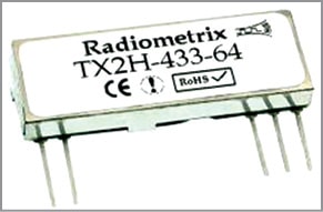
Depending upon applications, distance between detection stations and monitoring station can be hundreds of metres. In a large caravan site, this distance can even be a few kilometres. For this reason, RF transmitter and receiver modules are used in the design. Radiometrix (www.radiometrix.co.uk) TX2H transmitter module (Fig. 6) is used in the design. It is a 433.92MHz UHF FM transmitter module with 25mW power output, having a typical range of 500 metres, consuming only 23mA current.
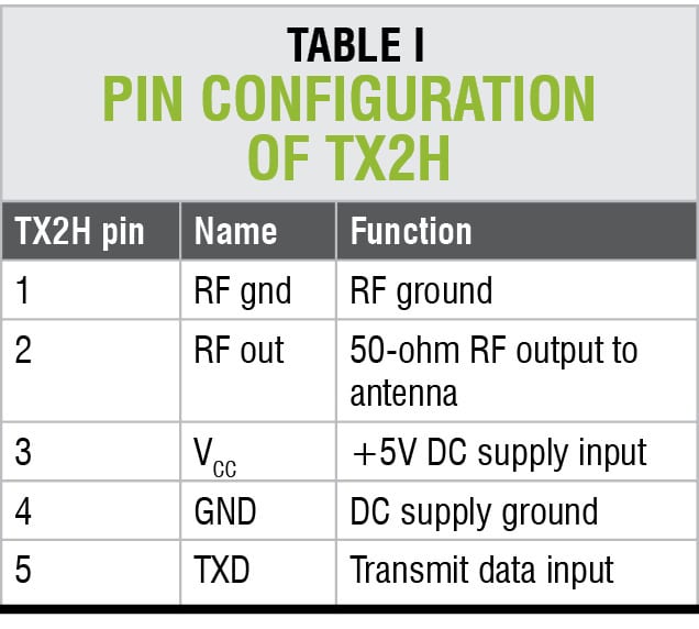
The module is powered from +5V supply and is connected to pin 17 or UART (TX) of the MCU. A helical loop or whip antenna can be used with the module. Length of the whip antenna should be 16.4cm from RF pin. Pin configuration of TX2H is shown in Table I. Gas detection stations can be powered from +5V mains adaptors, usually used to charge cellphones.
Receiver and monitoring station
Fig. 7 shows the circuit diagram of the monitoring station. It is built around 433MHz receiver module RX2A-433-64 (RX1), PIC18F45K22 MCU (IC2), 16×2 LCD (LCD1), transistor BC548 (T1), piezo buzzer (PZ1) and a few other components. In this design, PIC18F45K22 is used with LCD1 display and buzzer PZ1. It is clocked using an 8MHz crystal.
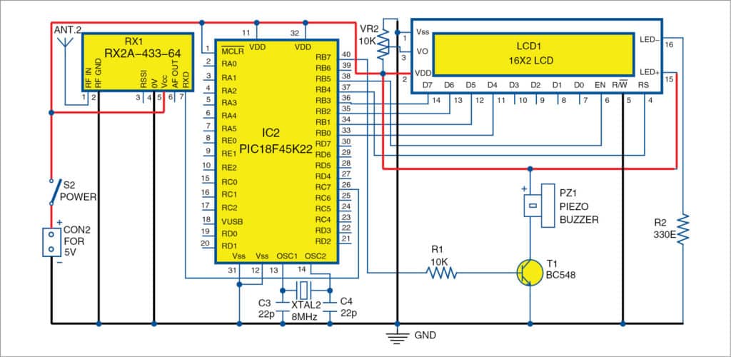
A compatible RX2A UHF receiver module (Fig. 8) is used at the monitoring station. This module has a sensitivity of -108dBm and operates with power supply from 2.7V to 16V.
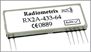
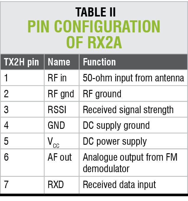
Typical current consumption is 11.6mA. Use of the module requires connection of an external antenna. Receiver data pin is connected to pin 26 or UART input (RX) of the MCU. Table II gives the pin configuration of RX2A.
Software
The software of the system has been developed using mikroC Pro for PIC language (www.mikroe.com). mikroC is a standard C-compatible language developed specifically for PIC MCUs. It has a rich library of functions, including RS-232, SPI, I2C, LCD, GLCD, TFT, SD card and PWM.
Download Source Folder
Detection station
At the beginning of DTransmitter.c program, threshold is set to 2500mV, so that the system is activated when LPG concentration level is approximately above 800ppm (Fig. 4). Then, Port B is configured as digital input and RA1 is configured as analogue input.
Port B internal pullups are enabled and UART is initialised to operate at 9600 baud rate. The rest of the program executes in an endless loop. Inside this loop, sensor output is read and converted into milli-volts. If sensor output is greater than 2.5V, station ID is read and the message ID=nn/ is sent to the monitoring station. Here, nn is station ID and / signifies terminator of data. The program repeats after one-minute delay.
Monitoring station
At the beginning of the program (MReceiver.c), interface between LCD and MCU is defined, and Ports B and C are configured as digital ports. Then, UART is set to 9600 baud rate and LCD is initialised. The program then enters an endless loop. Inside this loop, the program waits until data is received from a detection station, terminated with /. After receiving valid data, station ID of the station is displayed (Fig. 9) and the buzzer is activated. The program repeats after one-minute delay.

Construction and testing
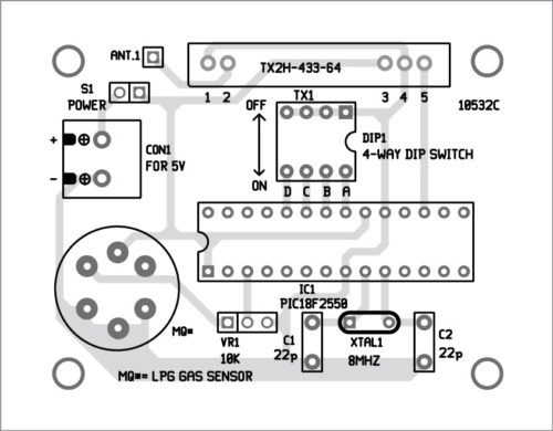
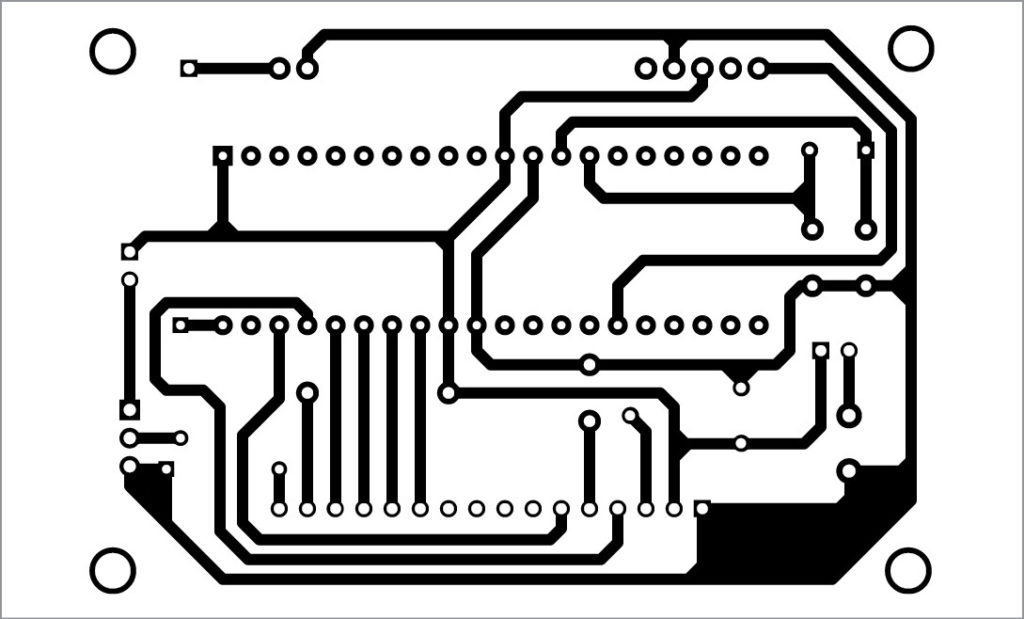
An actual-size PCB layout for the detection and transmitter circuit is shown in Fig. 10 and its components layout in Fig. 11. After assembling the circuit on the PCB, connect 5V across CON1. Load the hex file (DTransmitter.hex) of the transmitter to PIC18F2550 using a suitable programmer. Insert the IC to 20-pin IC base. Depending on requirement, you can assemble one circuit, or up to 16 similar circuits, with different IDs using DIP1 setting from 0 to 15.
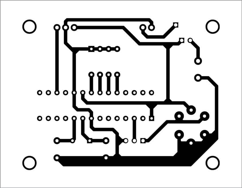
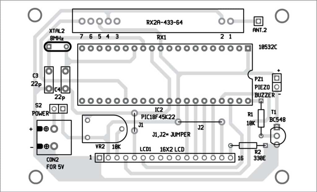
An actual-size PCB layout for the receiver and monitoring circuit is shown in Fig. 12 and its components layout in Fig. 13. After assembling the circuit on the PCB, connect 5V across CON2. Load the hex file (MReceiver.hex) of the receiver to PIC18F45K22 and insert the IC to 40-pin IC base. Assemble only one monitoring circuit and install it at a suitable location for monitoring.
Download PCB and Component Layout PDFs: Click Here
Also, check Smart Module for Air Quality, Gas, Temp & Humidity Monitoring with IoT Dashboard.
Prof. Dogan Ibrahim is PhD in digital signal processing and microprocessor applications from City University (UK). He is a fellow of Institution of Engineering Technology (UK)


hi,
where do i can get these two modules: 1. RX2A-433-64
2. TX2A-433-64 in india.
Hi ,
Found too many errors in the code, could you please help me out to debug the errors.
Kindly elaborate your query.
Hi,
The strcat in the code is not executing .so kindly help me that how to include string function in the code to display message.
Vasthi Model VT-90-O2, oxygen gas transmitter deficiency sensors are non-intrusive “Smart Oxy meter” sensors designed to detect and monitor O2 in air over the range of 0-25%.
One of the primary features of the sensor is its method of automatic calibration which guides the user through each step via instructions displayed on the backlit LCD.
Kindly suggest MCU other than PIC18F series, as this are higher devices
thank you
Nice