
In this project, we would be designing a Smart Card using Radio-frequency identification (RFID) tags. This smart card records previous journeys of the users and stations names. This project is based on the AEIOU heuristic framework of the Design Engineering Approach.
Design for Performance, Safety and Reliability is ensured in terms of fast response, restricted entry and authentic user.
Design for Ergonomics and Aesthetics is ensured in terms of hassle-free (no currency change) and a smart card that the user can carry in his wallet.
Design for Manufacturability and Assembly is ensured in terms of RFID machines. Also, previous journey records can be maintained for each user. More stations can be added to the system.
Design for Cost and Environment is addressed when mass production is considered and littering of tickets (even loss of ticket) is altogether removed.
This system can be further interfaced with the presently existing Printed Ticket system also.
Cost of the Project: Rs 1832/-
The same way we can also create Sim card based smart card readers.
Types of Smart Cards
Components Required
| Microcontroller | |
| Development Board | Arduino Uno |
| Sensors | |
| RFID Tag & Reader | RC522 |
| Display | |
| LCD | 16×2 Character LCD |
| Drivers | |
| L293D Motor Driver | dual H-bridge motor driver |
| Motor(5V) | |
| Connecting Wires | |
| Bread Board |
Here we have used RC522 RFID tag & it’s Reader. The MFRC522 is a highly integrated reader/writer IC for contactless communication at 13.56 MHz. The MFRC522 reader supports ISO/IEC 14443 A/MIFARE and NTAG. The MFRC522’s internal transmitter is able to drive a reader/writer antenna designed to communicate with ISO/IEC 14443 A/MIFARE cards and transponders without additional active circuitry. The receiver module provides a robust and efficient implementation for demodulating and decoding signals from ISO/IEC 14443 A/MIFARE compatible cards and transponders. The digital module manages the complete ISO/IEC 14443 A framing and error detection (parity and CRC) functionality. The MFRC522 supports MF1xxS20, MF1xxS70 and MF1xxS50 products. The MFRC522 supports contactless communication and uses MIFARE higher transfer speeds up to 848 KBd in both directions.
The following host interfaces are provided:
- Serial Peripheral Interface (SPI)
- Serial UART (similar to RS232 with voltage levels dependent on pin voltage supply)
- I2C-bus interface
LCD (Liquid Crystal Display)
Here we used 16×2 Character LCD Displays
Size: 84mm x 44mm x 12.1mm
Character Count by Lines: 16×2
Color: Dark on Yellow-Green
Type: Character LCD
L293D Motor Driver
L293D is a dual H-bridge motor driver integrated circuit (IC). Motor drivers act as current amplifiers since they take a low-current control signal and provide a higher-current signal. This higher current signal is used to drive the motors.
L293D contains two inbuilt H-bridge driver circuits. In its common mode of operation, two DC motors can be driven simultaneously, both in forward and reverse direction. The motor operations of two motors can be controlled by input logic at pins 2 & 7 and 10 & 15. Input logic 00 or 11 will stop the corresponding motor. Logic 01 and 10 will rotate it in clockwise and anticlockwise directions, respectively.
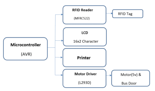
Enable pins 1 and 9 (corresponding to the two motors) must be high for motors to start operating. When an enable input is high, the associated driver gets enabled. As a result, the outputs become active and work in phase with their inputs. Similarly, when the enable input is low, that driver is disabled, and their outputs are off and in the high-impedance state.
Types of Smart Cards
- Magnetic stripe cards
- Optical cards
- Memory cards
- Microprocessor cards
Working of the Smart Card Technology:
The model works as follows:
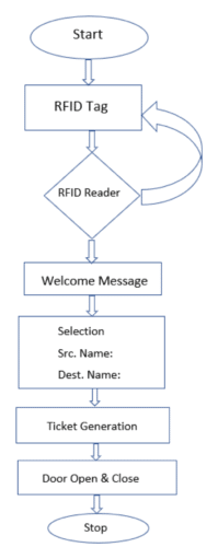
In the beginning, the display reads “GSRTC SMART CARD” – The Name Of Our Designed System.
When the RFID Tag is read by the Smart Card Reader, the machine would detect its unique Identification Number which serves as a security feature and a “WELCOME MESSAGE” would be displayed on the screen of the machine. After the Welcome Message, the personal information of the particular Customer that the card stores will be displayed on the screen containing Name, Phone Number, E-mail ID, etc. Other features may be added if desired.
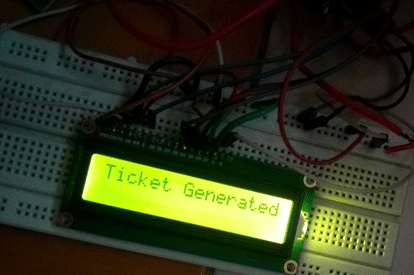
After the basic information, the system asks the user to enter into two columns respectively, the Source and the Destination Station “Src Name” and “Dest Name” implying the Starting Destination and Ending Destination. When the customer enters both the source and the destination, a ticket will be generated based on the preferences of the Customer and other information. The display then shows “Ticket Generated” without being into any Physical contact and contactless payment is done.
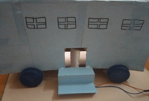
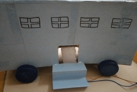
When the Ticket is generated, the Door of the Bus will be open for a small period of time and the access control is given so that the Customer can get in and then it is closed back again. Thus, the Door opens condition to a valid RFID authentication and a Ticket based on data entered is generated.
These Smart Cards are similar in size of Credit Cards and Debits Cards.
Nowadays, RFID tags are also coming up in mobile phones, and we can use these phones as our own contactless smart cards. This trend is very popular in United states and generally comes in Samsung smartphones.
Construction & Testing of the Smart Card

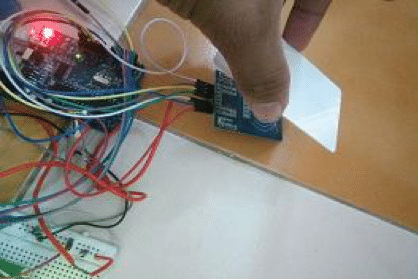
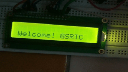
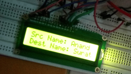
Flowchart
Software
Arduino version 1.6.6 (Arduino IDE operating system) is used for this project but as no directory change is made, the same can be achieved using any of the latest versions of the Arduino IDE. The IDE is available here.
The next section gives a brief insight into the pin denitions and input-output port details as well as programming details.
#include #include
#include
#include
// initialize the library with the numbers of the interface pins
LiquidCrystal lcd(7, 6, 5, 4, 3, 2);
#define SS_PIN 10
#define RST_PIN 9
const int inputPin3 = A0; // Pin 7 of L293D IC
const int inputPin4 = A1; // Pin 2 of L293D IC
RFID rfid(SS_PIN,RST_PIN);
int led = 13;
int power = 8;
int serNum[5];
int cards[][5] = { {140,91,70,213,68} };
bool access = false;
void setup()
{
Serial.begin(9600);
SPI.begin();
rfid.init();
pinMode(led, OUTPUT);
digitalWrite(led, LOW);
pinMode(inputPin3, OUTPUT);
pinMode(inputPin4, OUTPUT);
// set up the lcd’s number of columns and rows:
lcd.begin(16,2);
//lcd.print(“Key Pressed:”);
lcd.print(“GSRTC SMART CARD”);
Serial.print(“GSRTC SMART CARD”);
delay(2000);
lcd.clear();
}
void loop()
{
if(rfid.isCard()){
if(rfid.readCardSerial()){
Serial.print(rfid.serNum[0]);
Serial.print(” “);
Serial.print(rfid.serNum[1]);
Serial.print(” “);
Serial.print(rfid.serNum[2]);
Serial.print(” “);
Serial.print(rfid.serNum[3]);
Serial.print(” “);
Serial.print(rfid.serNum[4]);
Serial.println(“”);
for(int x = 0; x < sizeof(cards); x++){
for(int i = 0; i < sizeof(rfid.serNum); i++ ){
if(rfid.serNum[i] != cards[x][i]) {
access = false;
break;
} else {
access = true;
}
}
if(access) break;
}
Serial.print(“\n”);
}
if(access)
{
lcd.setCursor(0, 1);
lcd.print(“Welcome! GSRTC”);
delay(3000);
lcd.clear();
Serial.println(“Welcome! GSRTC”);
lcd.clear();
lcd.setCursor(0, 0);
lcd.print(“Src Name: Anand”);
lcd.setCursor(0, 1);
lcd.print(“Dest Name: Surat”);
Serial.print(“Src Name: Anand”);
Serial.print(“\n”);
Serial.print(“Dest Name: Surat”);
delay(3000);
lcd.clear();
lcd.print(“Ticket Generated”);
Serial.print(“\n”);
Serial.print(“Ticket Generated”);
delay(3000);
lcd.clear();
digitalWrite(led, HIGH);
delay(500);
digitalWrite(led, LOW);
digitalWrite(power, HIGH);
delay(500);
digitalWrite(power, LOW);
// motor to open the gate
digitalWrite(inputPin3, HIGH);
digitalWrite(inputPin4, LOW);
delay(500);
digitalWrite(inputPin3, HIGH);
digitalWrite(inputPin4, HIGH);
delay(5000);
digitalWrite(inputPin3, LOW);
digitalWrite(inputPin4, HIGH);
delay(500);
digitalWrite(inputPin3, HIGH);
digitalWrite(inputPin4, HIGH);
delay(5000);
}
else
{
lcd.setCursor(0, 1);
lcd.print(“Not allowed!”);
delay(3000);
lcd.clear();
Serial.print(“\n”);
Serial.println(“Not allowed!”);
digitalWrite(led, HIGH);
delay(500);
digitalWrite(led, LOW);
delay(500);
digitalWrite(led, HIGH);
delay(500);
digitalWrite(led, LOW);
}
}
rfid.halt();
}
Project by Manthan Patel, Jay Joshi, Jenish Bhanderi and Morvin Bhungaliya under the guidance of Prof. Geetali Saha, EC Department, GCET.


Innovatie, constructive and useful idea and project
Hi,
Its a beautiful project, would u pleas share the circuit diagram of this project.
regards
sushil