
Do a Google search on “build your own robot” and you’ll find a treasure trove of kits, articles, and videos. Have you ever wanted to give this a try? An engineer at Maxim with a long-standing interest in robotics found a way to build his own using one of the company’s featherboards. Presented with an opportunity to write some example code for the Bosch Sensortec BMI160 inertial measurement unit (IMU) on Maxim’s MAX32630FTHR board, the engineer jumped at the chance to build his own self-balancing robot.
The engineer started his project by configuring the on-board IMU, which estimates a pitch angle from vertical to help the robot stay straight. Should the robot drift away from the vertical point, the control loop would direct the DC motors to keep the base of the robot under its center of gravity. The IMU samples data from the accelerometer/gyroscope and runs it through a complementary filter to produce an estimated feedback signal (providing the estimated pitch of the robot at a given time) for the control loop. The complementary filter, which fuses accelerometer and gyroscope data into a single feedback signal, provides an easier-to-use option than the traditional Kalman filters that can also be used for this purpose.
Performs Floating-Point Calculations Quickly
The MAX32630FTHR board is designed to help engineers quickly implement battery-optimized solutions with the MAX32630 ARM Cortex-M4F microcontroller. This microcontroller features a floating-point unit and performs calculations quickly. With this feature, the engineer didn’t have to perform any approximations to generate the pitch estimates for his robot. The board also features 512K of SRAM, which the engineer used for data logging while the control loop was running. He used, for example, a sample rate of 1.25ms (800Hz) and recorded 14400 samples of the accelerometer horizontal and vertical axis, the gyroscope x-axis, and the pulse-width modulation (PWM + DC) sent to each motor. All of this used only 45% of the available RAM, consisting of 18 seconds of data. Since the board provides a micro SD card connector, the engineer was able to write the saved data to an SD card as a CSV file and then remove the card for data analysis on a PC.
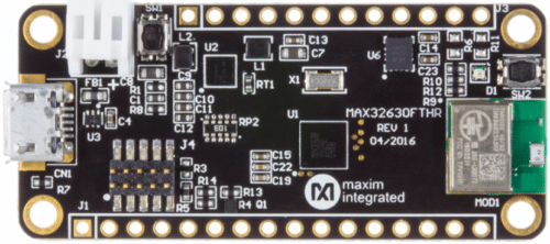
While the engineer could have used various other microcontrollers as the underlying technology for his robot, he chose the MAX32630FTHR board based on all of the features it includes. The 0.9-inch x 2.0-inch board includes a MAX14690 power management IC, a dual-mode Bluetooth module, and a 6-axis accelerometer/gyroscope. It’s ideal for fast proofs-of-concept and early software development of applications like wearable medical patches, portable medical devices, fitness monitors, sports watches, sensor hubs, and, of course, robots.
Control Loop
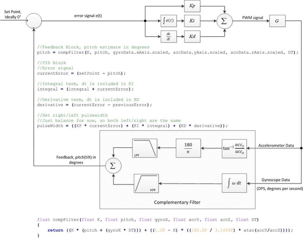
Figure 1 demonstrates the control loop used for this project.

PID Controller
The forward path of my control loop implements a Proportional, Integral, and Derivative (PID) controller with the output being the duty cycle of the PWM signals driving the MAX14870 H-Bridge for each motor. The PID controller is one of the most widely used controllers in systems today. One of the reasons for its wide use is the ability to ‘tune’ the system by adjusting the PID gains without having a well defined model of the system. This is usually done from an intuitive feel of how changing the PID gains will affect the system and how the system should respond to a disturbance. Procedures such as the Zeigler-Nichols method have been developed to guide that intuition.
For a very good and practical introduction to using a PID controller in a robotic system I recommend the following link: A PID Controller For Lego Mindstorms Robot. The author does an excellent job of introducing each term and the implications of adjusting that term. A variant of the Ziegler-Nichols method of tuning a PID controller is also given.
Complementary Filter
The feedback path of my control loop uses a Complementary filter. As I mentioned in the introduction, I first learned about this filter in the referenced article. In addition, I found the following references helpful.

1 Reading a IMU Without Kalman: The Complementary Filter
- The Balance Filter
I found the last reference fairly complete in its description of the pros and cons of using each sensor (accelerometer/gyroscope) individually, and why the complementary filter is a suitable solution for ‘fusing’ the two together. The end result is the combination of high pass filtering the integration of angular velocity (gyroscope output), which gives you angular position in that plane, combined with low pass filtering an angle estimate obtained by taking the tangent inverse of the horizontal and vertical components of acceleration in the same plane.
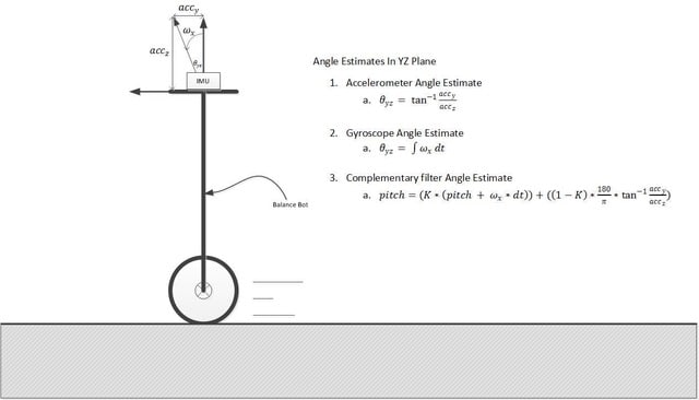
In other words, the Complementary filter combines the gyroscope data for very dynamic angular measurements with the accelerometer data for static angular measurements to produce a reliable feedback signal. See Figure 2 for sensor angle estimations.
Filter Results
Some of the benefits of using the MAX32630FTHR is the ARM Cortex-M4F CPU at the heart of the MAX32630 MCU, 512K of SRAM available to the application, and the microSD card slot available for data logging. To generate the following plots I recorded 14400 samples of the accelerometer horizontal and vertical axis, the gyroscope x-axis, and the pulse width (PWM +D.C.) sent to each motor. The sensor data is saved as floats and the pulsewidth as a signed 32 bit integer. Each of these variables takes four bytes a piece, so for total RAM used for data logging we have the following:
RAM = ((4bytes/var * 4vars) * num_samples) = 230.4KB
Which is only 45% of the available RAM. With a sample rate of 1.25ms (800Hz), 14400 samples ends up being 18 seconds worth of data. The actual size of the file saved to the SD card ends up being considerably larger due to additional data be calculated from the sensor data recorded. See the function ‘saveData’ in the mbed code below.
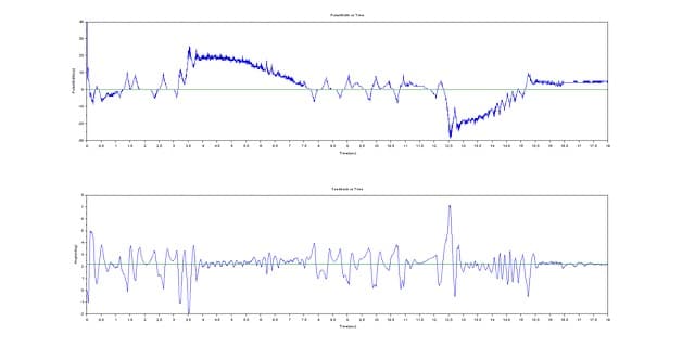
Figure 3 shows the results of manipulating a MAX32630FTHR by hand.
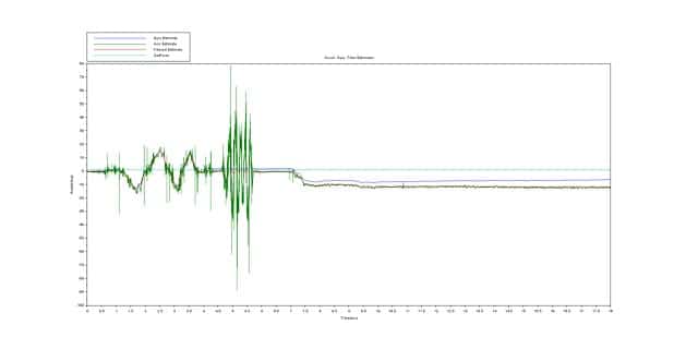
This measurement was an attempt to show the filters ability to remove the drift associated with the gyro and filter out the noise associated with the accelerometer while still providing a reliable pitch estimate for the feedback signal.
Below is a description of what actions were done in sequential order to generate the plot shown in Figure 3. Figures 4 -6 are zoomed in versions of Figure 3.
- From ~0.7 to 4 seconds the pcb was rolled on the x-axis of the gyroscope to produce an angular velocity. You can see from Figure 4 that the output of the filter tracks the integration of the gyroscope data while filtering out the accelerometer data.
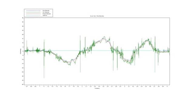
Figure 4: Rolling pcb - From ~4 seconds to 4.75 seconds there was relatively no movement.
- From ~4.75 to 5.75 the pcb was shaken laterally through the y-axis of the accelerometer. Figure 5 once again shows the accelerometer data being filtered. The coefficient associated with the complementary filter can probably be increased closer to one to remove the small ripples on the filter output due to the accelerometer data in this timeframe.
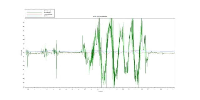
- From ~5.75 to 7 seconds there was relatively no movement.
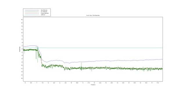
- From ~7 seconds on, the pcb was held at a constant pitch of ~12 degrees. Figure 6 shows relatively static movement of the pcb, so we can see a definite drift in the integration of the gyro data, however, our filter output tracks the accelerometer data at 12 degrees. The filter output, our feedback signal, never approaches the setpoint because these measurements were taken by manually manipulating the attitude of a MAX32630FTHR board not installed on the robot.
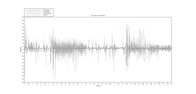
Figures 7 and 8 are plots of data recorded while running the robot. In Figure 7, the accelerometer data is gray despite the legend stating green. The accelerometer data was selected when creating the image, making it easier to see the gyro data and filter output.
Tuning The Loop
One note on tuning this loop. I found it easier to adjust the coefficient for the Complementary filter with the MAX32630FTHR removed from the robot. With the pcb removed, you can manipulate the board as you will and see how the output of your filter tracks the individual sensor angle measurements. The coefficient of the filter should be less than one as mentioned in the articles, but how much less than one depends on your sample rate and the desired time constant of the filter. Once your filter is behaving correctly, then you can tune the PID loop. There is no point in tuning the PID loop if the feedback path isn’t working.
Next Steps
- Address backlash due to gearbox imperfections
- Integrate Ultrasonic sensor for maintaining distance from object
- Integrate sensor for line following while balancing
- Design app specific PCB using MAX32630
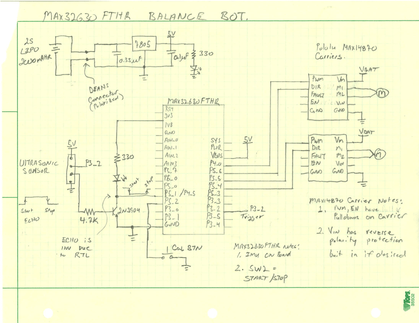
Schematic


Nice article but oddly disembodied. I think it is weird that the engineer is not identified, without explanation. If the article is about the design, then no need to mention the engineer at all, but since you talk about it from the engineer’s angle, why not give him the credit?
Design has become commoditized but the creative work is still done by people. Until the robots take over, let’s salute the humans.
The engineer should have written the article himself on his own site and do a decent job instead of this