

The new design enables isolated multi-output power supplies for automotive and industrial applications with built-in protection features.
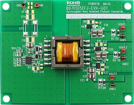
A reference design from ROHM demonstrates an isolated flyback power supply for automotive and industrial applications. The power supply provides three isolated outputs of 6.2 V, 16.5 V and 6.2 V respectively, from an input voltage of 8 V to 32 V with a maximum output power of 6 W. Power efficiency is 75 per cent at 2 W output power, while standby power consumption is limited to 40 mW.
This solution is based on an isolated flyback topology, which does not require an optocoupler or a third winding on the transformer for feedback regulation. Primary-side regulation measures the flyback voltage at the output, reducing the number of components required for the power-supply design.
The converter incorporates a built-in switching MOSFET that operates at an average switching frequency of about 363 kHz. The output voltage is determined by two resistors and the transformer turns ratio. Adaptive on-time control is used, as well as pulse-frequency modulation (PFM) mode for efficient operation at light loads.
A number of protection features have been incorporated to improve reliability. These include undervoltage lockout (UVLO), overcurrent protection (OCP), thermal shutdown (TSD), REF pin open protection, short circuit protection (SCP) and battery short circuit protection (BSP). The system starts operating once the VIN pin voltage exceeds 3.4 V (detection voltage for UVLO) and the enable pin voltage exceeds 2 V.
The design is intended for isolated power supply systems used in automotive electronic and industrial applications. The VIN pin supports input voltages up to 42 V, while the switching pin supports up to 60 V. In addition, it can operate in temperatures ranging from -40°C to +125°C.
Hardware resources as well as supporting documents have been included in the reference design to support evaluation and development of isolated power-supply designs. They include schematics, PCB files and connection diagrams.
For more information, click here.