 This simple RF signal detector circuit can be used to trace the presence of RF signals and electromagnetic noise in your residential area, office or shop. It can be a useful tool while testing or designing RF circuits. It can also be used to detect electrical noise in your premises.
Electromagnetic noises can be produced by sparking in electrical installations or other sources. To detect the presence of RF signal or noise, you need a wide-band receiver that can capture these signals.

Circuit and working
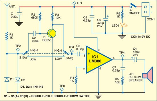
Fig. 1 shows the circuit of RF signal detector. It consists of a telescopic antenna, input protection resistor (R1), two diodes (D1 and D2), selector switch (S1), pre-amplifier with a low-noise and high-gain transistor (T1), and audio amplifier IC LM386 (IC1).
Switch S1 is used to select between high and low sensitivities of the circuit. When high sensitivity is selected, gain of the transistor stage with T1 is added to gain of IC LM386. When low sensitivity is selected, gain of only IC LM386 is used, which is around 20. In order to keep the circuit simple and compact, no volume control is included.

When there is a strong electromagnetic signal near the antenna, e.g., from a mobile phone, telephone or electrical motor, you can hear audible sound from the speaker (LS1). As you bring this detector closer to the RF or noise-transmitting source, the sound from the speaker becomes louder. Thus you can trace the exact location of the source. You can use an antenna of appropriate shape and length to increase the range of reception and sensitivity.
Construction and testing
Normally, the circuit does not need any adjustment. But it is preferable to keep the collector-emitter voltage of T1 around half the power supply voltage and the collector current at least 1 mA. The preferred power supply range is 9-15 V DC. If the circuit produces motor boating noise with AC mains adapter, use a battery instead to reduce the noise. The circuit works well with a single 9V PP3 or 6F22 type battery.


Download PCB component PDFs: click here
Download component layout PDFs: click here
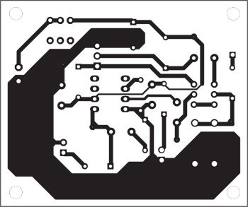
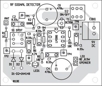
A single-side PCB for the RF signal detector is shown in Fig. 2 and its component layout in Fig. 3. Assemble the circuit on a PCB to minimize time and assembly errors. Carefully assemble the components and double-check for any overlooked error. Use IC base for IC LM386. Before inserting the IC, check the supply voltage.
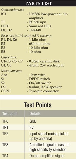
To test the circuit for proper functioning, using test points TP0 and TP1 on the PCB, first check whether power supply to the circuit is correct. Place some RF source near the antenna and through oscilloscope verify whether the signals are being received at TP2.
You can use your mobile phone as the RF source. Dial any number and place the phone near the antenna. Using switch S1 select high sensitivity for the circuit and check the amplified signal at TP3. The final output can be checked at TP4. Make sure that the RF source is continuously radiating while you check all the test points.
Feel interested? Check out more interesting project ideas in the circuit section.


is this circuit was tested????????
Yes, the circuit is fully tested.
WHAT ARE THE PRINTING DIMENSIONS OF THE PCB
Pls send me details who has this detector as i want to detect a microphone at my home or call me @9310048334
how the user of the circuit will know that…..a frequency(low or high), is present.??????
it does not have any display, then how will we get to know
HOW YOU TEST THE CIRCUIT…BY USING ANY TOOLS OR MANUALLY?
PLEASE HELP ME OUT .
can this circuit be used for AC main voltage
Hi I need help to build portable high voltage DC power supply with following specifications Input voltage: 85 to 264 VAC Output voltage: 0 to 5000or10000 VDC output current:1mA(max) ripple&noise: 500mV with output voltage control knob for my research purpose can anyone help me?
How doe sthis Circuitt Works???
Hii EFY team..!
I do have a request from.my side,that I need a circuit which I was unable to get it from my search engine..can u get it for me…..if possible provide me a circuit design for an electronic device detector…