


 When using a servo motor in a project, if the servo motor does not respond as per the input, how to make sure that the fault is not in the servo motor but the circuit or logic? One way is to isolate the servo motor from the circuit and check its proper working by feeding it pulses of varying width and checking the angle that the servo motor turns to. For example, a 1.5ms pulse should make the motor turn to a 90-degree position (neutral position).
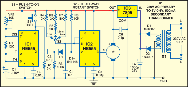
The circuit presented here generates pulses of varying widths. It is built around two NE555 timer ICs (IC1 and IC2) and a few discrete components. Timer IC1 is configured as an astable multivibrator with a time period of 20 ms. Every 20 ms, the astable provides a very sharp negative pulse to trigger IC2. Timer IC2 is configured as a monostable multivibrator that produces 1ms, 1.5ms and 2ms long pulses to rotate the servo motor (M1).
Pin 4 of IC1 is pulled down by resistor R2. When switch S1 is pressed, the astable multivibrator triggers the monostable to produce a pulse as per the position of switch S2. Switch S2 can select resistors R4, R5 and R6 together, and R7 to produce monostable pulse output of 1 ms, 1.5 ms and 2 ms, respectively. Preset VR1 is used to set the time period of IC1 to 20 ms.

Using switch S2, select the monostable time period as 1 ms, 1.5 ms or 2 ms and press switch S1. The servo motor should rotate to extreme left, middle or extreme right, respectively.
For more circuit articles: click here
