AM radios are still used for capturing transmissions from long distances (DX reception). But AM radios normally require long (10-30m) outdoor antennae. That is easy if you live in a village but not always practical in urban environments. Antennae of 2-5m length are easy to install and maintain but the signal from them can be very weak.
If you have no option but to use a relatively short antenna, you can improve the AM reception by adding the proposed low-noise antenna preamplifier for AM signals. Its operation range is 150-1700 kHz, covering the long-wave (LW) and medium-wave (MW) ranges.
Circuit and working
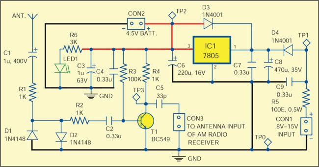
Fig. 1 shows the circuit of antenna preamplifier for AM radios. The input of the preamplifier is protected with capacitor C1, resistor R1, and diodes D1 and D2. Transistor T1 required for this application should be low-noise with moderate or high gain. For LW and MW ranges, BC550, BC547 and similar transistors will work well. It is important to keep the collector current at least 2 mA. In most cases, 2-5mA current is appropriate and can be adjusted with resistor R3. Larger currents, e.g. 10 mA, may improve the volume but reduce the battery life. Capacitor C2 separates the preamplifier from the AM radio. The power supply is +5V from the regulator 7805 (IC1). AC or DC power supply in the range of 8-15V may be applied to connector CON1.
The working of the circuit is simple. The preamplifier circuit provides a gain higher than 10 in the LW and MW range. The amplified signals are fed to antenna input of the AM radio receiver for better reception. The circuit can also work for short-wave (SW) range, depending on the quality of practical implementation.
Construction and testing
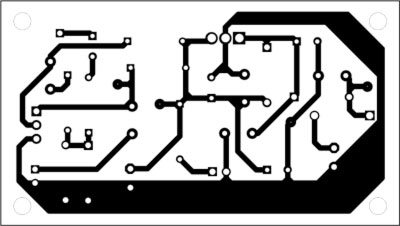
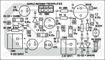
An actual-size, single-side PCB for the antenna preamplifier is shown in Fig. 2 and its component layout in Fig. 3. Assemble the circuit on a PCB to minimise assembly errors and save time. Carefully assemble the components and double-check for any overlooked error.
Download PCB and component layout PDFs: click here
The antenna should be at least 2m long and preferably mounted outside the building at least half a metre away from the walls in order to have noticeable improvement in reception. If you keep the antenna near walls or electrical cable installation, there may be reception issues and the antenna may capture too much noise. When there is possibility of lighting storms in the area, the antenna must be disconnected from the preamplifier.
The preamplifier can work off a 4.5V dry battery connected to connector CON2. Use of batteries in the range of 3V to 15V is recommended because the mains power supply may introduce some noise.
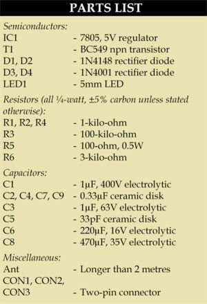
The preamplifier does not use expensive components. It will work immediately after proper assembly is done and show improvement in the reception of stations with low level of AM signal. The improvement depends on the location and length of the antenna. If you use the antenna in a room, you should put it on a window in order to increase the useful signal and reduce noise from other installations in the building.
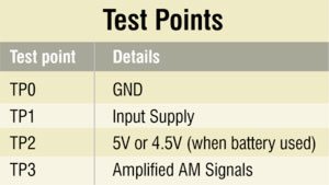
To test the circuit for proper functioning, check the input supply at test point TP1 with respect to TP0. The 5V supply to the preamplifier can be checked at TP2. Test the gain of the circuit by giving some input signal, using ordinary sinusoidal signal generator, to the preamplifier and checking the output at TP3, using an oscilloscope. For a 10mV, 1MHz signal at the input (antenna), you should get around 100 mV at TP3.
The author worked as a researcher and assistant professor in Technical University of Sofia (Bulgaria) and as lecturer and expert-lecturer in Kingdom of Morocco. Now he is an electronics engineer in the private sector in Bulgaria


