


An automatic bathroom light Circuit can be made in several ways, depending on your preference and budget. Some of the options make use of either a motion sensor, a smart switch, an occupancy sensor, or a photo sensor.
The simple system proposed here makes use of a small magnet fixed in the bathroom door’s frame and a reed switch with normally open contacts as the sensor on the bathroom door, just opposite the magnet. So, whenever you open the door, the reed switch will move away from the magnet.
Note: Be sure to consult a qualified electrician if you’re not comfortable with electrical work or if you need help with installation. Safety should always be your top priority when working with electricity.

Automatic Bathroom Light Circuit Diagram
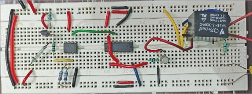
The author’s prototype is shown in Fig. 1 and the circuit diagram is shown in Fig. 2.
The circuit comprises step-down transformer X1, a normally closed type of reed switch, bridge rectifier BR1, transistor BC557 (T1), 5V voltage regulator LM7805 (IC1), a small magnet, op-amp 741 (IC2), decade counter 4017 (IC3), transistor 2N2219 (T2), 5V single changeover relay RL1, and a few other components.
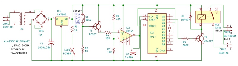
The circuit needs 5V DC o work, which can be derived from the 230V AC primary to 9V, 500mA step-down transformer X1. The 9V AC from X1 goes to bridge rectifier BR1 for rectification and is filtered by capacitor C1. The rectified and filtered voltage is regulated to 5V DC by IC LM7805, which is indicated by the glowing LED1.

Automatic Bathroom Light Working
When the bathroom door is closed, the magnet and the reed switch are near each other, reed switch contacts are open, and BC557 transistor T1 does not conduct. Hence voltage at pin 3 of IC2 remains lower than the reference voltage at pin 2 (around half of the supply voltage), output of op-amp IC2 at its pin 1 remains low, and decade counter 4017 (IC3) does not get any clock signal.
When the door is opened, the magnet and the reed switch move away from each other, the reed switch contacts close, and transistor T1 conducts. Hence voltage at pin 3 of IC2 goes higher than the reference voltage at pin 2, output of op-amp IC2 at its pin 1 goes from low to high, and decade counter 4017 (IC3) gets a clock signal. Clock Q0 of 4017 shifts to Q1 output and relay driver transistor T2 conducts. As a result, relay RL1 energizes and the bathroom light gets connected to 230V AC and glows.
After entering the bathroom, when you close the door again, the magnet and the reed switch again come near each other. Reed switch contacts open and transistor T1 does not conduct. Hence voltage at pin 3 of IC2 goes lower than the reference voltage at pin 2, output of op-amp IC2 at pin 1 goes from high to low, and decade counter 4017 (IC3) does not get any clock signal. Clock Q1 of 4017 does not shift to Q2 output, the relay remains energized, and the bathroom light keeps glowing.
| Parts List | |
| Semiconductors: | |
| IC1 | – LM7805, 5V voltage regulator |
| IC2 | – Op-amp 741 |
| IC3 | – 4017 decade counter |
| BR1 | – 1A bridge rectifier |
| LED1 | – 5mm LED |
| T1 | – BC557 PNP transistor |
| T2 | – 2N2219 NPN transistor |
| Resistors (all 1/4-watt, ±5% carbon): | |
| R1, R2 | – 1-kilo-ohm |
| R3 | – 680-ohm |
| R4 | – 10-kilo-ohm |
| R5, R6 | – 12-kilo-ohm |
| Capacitors: | |
| C1 | – 1000μF, 35V electrolytic |
| C2 | – 1μF, 16V electrolytic |
| Miscellaneous: | |
| CON1-CON3 | – 2-pin connector |
| S1 | – Small normally closed-type glass reed switch |
| RL1 | – 5V, 1CO relay |
| X1 | – 230V AC primary to 9V, 500mA secondary transformer |
| – A small magnet | |
When you open the bathroom door once again to exit, the magnet and the reed switch move away from each other, the reed switch contacts close, and transistor T1 conducts. Hence voltage at pin 3 of IC2 goes higher than the reference voltage at pin 2, output of op-amp IC2 at its pin 1 goes from low to high, and decade counter 4017 (IC3) gets a clock signal. Clock Q1 of 4017 now shifts to Q2 output and relay driver transistor T2 stops conducting. As a result, relay RL1 de-energizes, and the bathroom light disconnects from 230V AC and goes off.

Thank you very much for the useful circuit.
Sir, can I use 10kΩ for R5&R6 instead of 12kΩ?
Can I use CL100 in TO-39 metal case package for transistor T2 instead of 2N2219 in TO-39?
Yes you can use 10kΩ for R5and R6 instead of 12kΩ?
Also can use CL100 in TO-39 metal case package for transistor T2 instead of 2N2219 in TO-39.
Regards
Hello sir,
I made this circuit at my home and I found that the tranistor T1 (BC557) was not pull down at the collector terminal.
Can you help me that it is working without Pull down resistor. Because when i was making that circuit without pull down that my relay was chattering (ON and OFF rapidly). After Pull down, it works properly as you mention. I put this circuit also in my bathroom and it works perfectly. Thanks for giving such an excellent circuit idea.