


 Here is a simple circuit that can be used to test a crystal before using it in a circuit. The circuit is built around two BC547 transistors (T1 and T2) and a few discrete components.
The oscillator circuit formed by transistor T1, resistors R1 and R2, and capacitors C1 and C2 oscillates if a good crystal is connected to the test points marked as CUT (crystal under test). The output from the oscillator is rectified by diode D1 and filtered by capacitor C3. The positive voltage appearing across the capacitor is fed to the base of transistor T2, causing it to conduct.
Testing of a crystal is simple: Insert the crystal at CUT points shown in the circuit diagram and press test switch S1. If LED1 glows, your crystal is good and you can use it in a circuit.

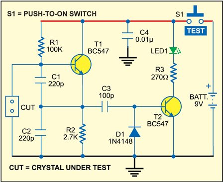
The crystal tester circuit is powered by a standard 9V battery. Push-to-on switch S1 is included to prolong the battery life but it’s not needed if you use a socket for the crystal under test.
Assemble the circuit on a general-purpose PCB and enclose in a suitable small cabinet. Fix the two-pin connector, LED1 and test switch on top of the cabinet. Fix the 9V battery inside the cabinet.
Note. You can use 2N3563 transistors instead of BC547.
Please give more information on crystal tester s that it could be helpful.
What type of information are you looking for?
I am not able to get the output. Could you pls help me with the procedure